Ford Ecosport: Exterior Lighting / Removal and Installation - Stoplamp Switch
Removal
-
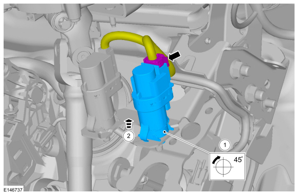
NOTICE: Do not press, pull or otherwise move the brake pedal while installing the stoplamp switch and cruise control deactivation switch. Install these switches with the booster push rod attached to the brake pedal and with the brake pedal in the at-rest position. Installing these switches with the brake pedal in any other position results in incorrect adjustment and damages the switches.
While gently pushing the stoplamp switch down, rotate the stoplamp switch clockwise approximately a quarter turn to remove the stoplamp switch. Disconnect the stoplamp switch electrical connector and the stoplamp switch..
 |
Installation
-
NOTICE: Do not press, pull or otherwise move the brake pedal while installing the stoplamp switch and cruise control deactivation switch. Install these switches with the booster push rod attached to the brake pedal and with the brake pedal in the at-rest position. Installing these switches with the brake pedal in any other position results in incorrect adjustment and damages the switches.
To install, reverse the removal procedure.
 Removal and Installation - Reversing Lamp
Removal
NOTE:
RH side reversing lamp assembly shown, LH side similar.
Remove the rear bumper cover.
Refer to: Rear Bumper Cover (501-19 Bumpers, Removal and Installation)...
 Removal and Installation - Trailer Module (TRM)
Removal
NOTE:
Removal steps in this procedure may contain installation details.
NOTE:
If installing a new module, it is necessary to
upload the module configuration information to the diagnostic scan tool
prior to removing the module...
Other information:
Ford Ecosport 2014-2026 Service and Repair Manual: Removal and Installation - Rear Door Skin Panel
Special Tool(s) / General Equipment Grinder Hot Air Gun Knife Locking Pliers Materials Name Specification Metal Bonding AdhesiveTA-1, TA-1-B, 3M™ 08115, LORD Fusor® 108B, Henkel Teroson EP 5055 - Seam SealerTA-2-B, 3M™ 08308, LORD Fusor® 803DTM - Flexible Foam Repair3M™ 08463, LORD Fusor® 121 -..
Ford Ecosport 2014-2026 Service and Repair Manual: Description and Operation - Communications Network - System Operation and Component Description
System Operation System Operation *.sttxt { visibility: hidden; } *.stcallout { visibility: visible; } E356703 ..
Categories
- Manuals Home
- 2nd Gen Ford Ecosport Service Manual (2014 - 2026)
- Removal and Installation - Catalytic Converter
- Removal and Installation - Starter Motor
- Body and Paint
- Removal and Installation - Fuel Pump and Sender Unit
- Engine
Removal and Installation - Front Stabilizer Bar
Special Tool(s) / General Equipment
Tie Rod End Remover Transmission JackRemoval
NOTICE: Suspension fasteners are critical parts that affect the performance of vital components and systems. Failure of these fasteners may result in major service expense. Use the same or equivalent parts if replacement is necessary. Do not use a replacement part of lesser quality or substitute design. Tighten fasteners as specified.
NOTE: Removal steps in this procedure may contain installation details.
NOTICE: Disconnect the b