Ford Ecosport: Exhaust System - 2.0L Duratec-HE (129kW/175PS) / Removal and Installation - Catalytic Converter
Special Tool(s) /
General Equipment
Removal
NOTE:
If the catalytic converter is not being replaced, the HO2S
and the catalyst monitor sensor do not need to be removed from the
catalytic converter. Disconnecting the electrical connectors is still
necessary.
-
Refer to: Health and Safety Precautions (100-00 General
Information - 2.0L Duratec-HE (129kW/175PS), 2.0L Duratec-HE
(125kW/170PS) – MI4, 2.0L Duratec-HE Flex Fuel (129kW/175PS))
.
-
Remove the HO2S .
Refer to: Heated Oxygen Sensor (HO2S) (303-14C Electronic Engine
Controls - 2.0L Duratec-HE (129kW/175PS), Removal and Installation).
-
Remove the catalyst monitor sensor.
Refer to: Catalyst Monitor Sensor (303-14C Electronic Engine Controls -
2.0L Duratec-HE (129kW/175PS), Removal and Installation).
-
Remove the rear driveshaft.
Refer to: Driveshaft (205-01 Driveshaft, Removal and Installation).
-
Remove the RH front halfshaft.
Refer to: Front Halfshaft RH - 2.0L Duratec-HE (125kW/170PS) – MI4, AWD
(205-04 Front Drive Halfshafts, Removal and Installation).
All vehicles
-
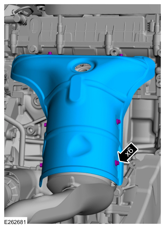
Remove the fasteners and catalytic converter shield.
-
NOTICE:
Make sure that the exhaust flexible pipe is not forcibly bent or twisted.
Remove the fasteners and catalytic converter shield.
Use the General Equipment: Cable Ties
-
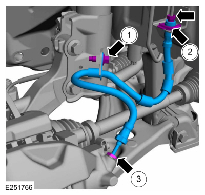
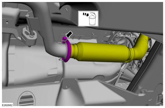
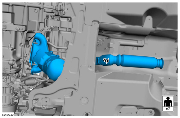
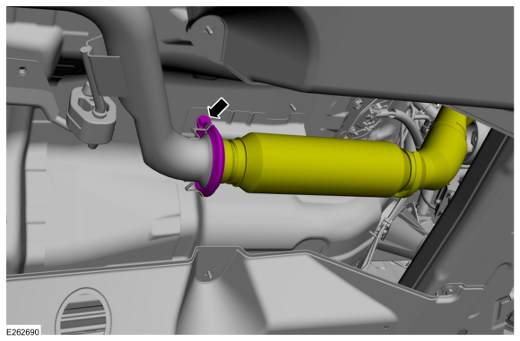
Remove and discard the muffler and catalytic converter flange clamp.
-
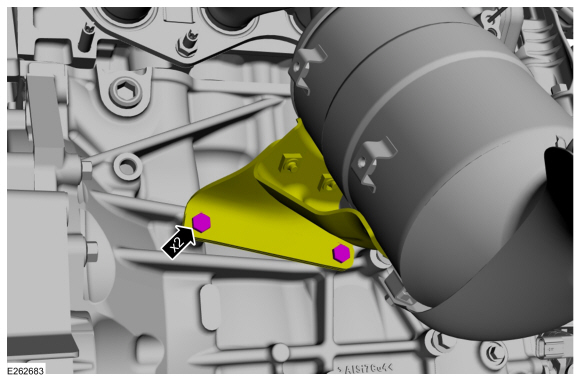
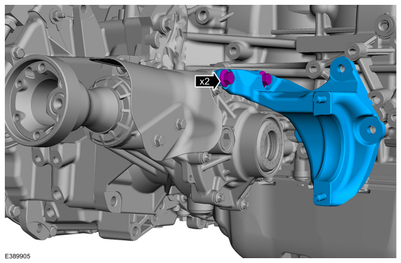
Remove the bolts and position aside catalytic converter mounting bracket.
-
Remove and discard the bolts.
-
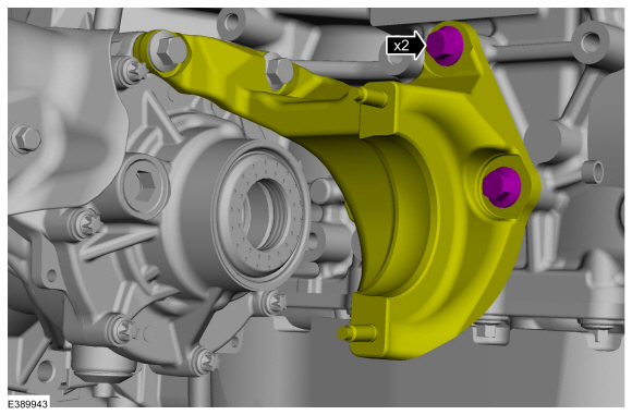
Remove the PTU to engine mounting bracket bolts.
-
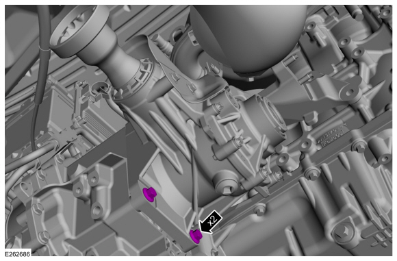
Remove the PTU mounting bolts.
-
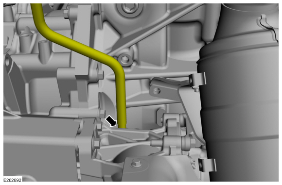
Disconnect PTU vent hose.
-
Remove the PTU to engine mounting bracket bolts and remove the bracket.
-
Remove the PTU mounting bolts and PTU.
-
Remove and discard the input seal RH .
Refer to: Transfer Case Input Shaft Seal RH (308-07B Transfer Case -
6-Speed Automatic Transmission – 6F35, Removal and Installation).
All vehicles
-
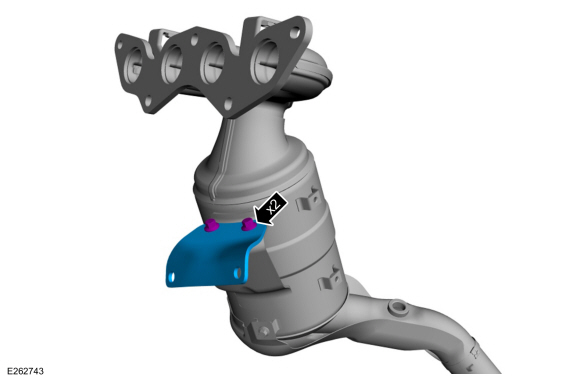
Remove the bolts and catalytic converter mounting bracket.
-
Remove the catalytic converter.
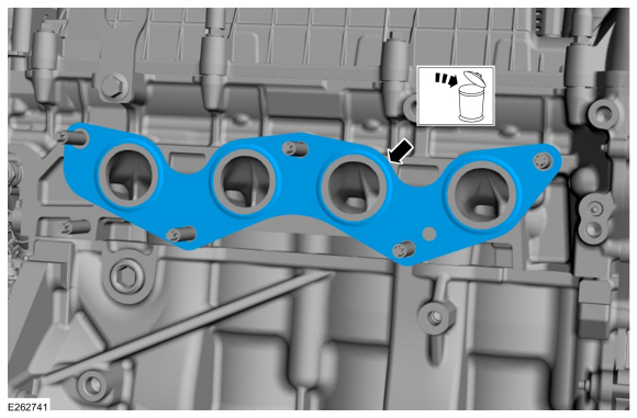
-
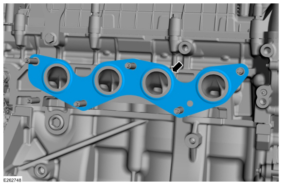
Remove and discard the gasket.
Installation
All vehicles
-
Install a new gasket.
-
Install the catalytic converter.
-
Install the bolts and catalytic converter mounting bracket.
Torque:
17 lb.ft (23 Nm)
-
Install the input seal RH .
Refer to: Transfer Case Input Shaft Seal RH (308-07B Transfer Case -
6-Speed Automatic Transmission – 6F35, Removal and Installation).
-
Install the PTU and the PTU mounting bolts.
Torque:
59 lb.ft (80 Nm)
-
Install the engine mounting bracket and bolts.
Torque:
35 lb.ft (48 Nm)
-
Connect PTU vent hose.
-
Install the PTU mounting bolts.
Torque:
59 lb.ft (80 Nm)
-
Install the PTU to engine mounting bracket bolts.
Torque:
35 lb.ft (48 Nm)
All vehicles
-
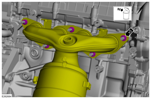
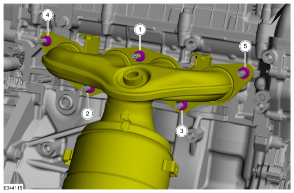
NOTE:
Tighten the catalytic converter bolts in this sequence.
Position the catalytic converter and install the nuts.
Torque:
Stage 1:
177 lb.in (20 Nm)
Stage 2:
41 lb.ft (55 Nm)
-
Install the bolt and position back catalytic converter mounting bracket.
Torque:
35 lb.ft (48 Nm)
-
Position the pipe and install the new catalytic converter flange clamp.
Torque:
18 lb.ft (25 Nm)
-
NOTICE:
Make sure the exhaust flexible pipe is not forcibly bent or twisted.
Position back the flex pipe and release the cable ties.
-
Install the catalytic converter shield and bolts.
Torque:
80 lb.in (9 Nm)
-
Install the RH front halfshaft.
Refer to: Front Halfshaft RH - 2.0L Duratec-HE (125kW/170PS) – MI4, AWD
(205-04 Front Drive Halfshafts, Removal and Installation).
-
Install the rear driveshaft.
Refer to: Driveshaft (205-01 Driveshaft, Removal and Installation).
-
Check the Transfer Case Fluid Level.
Refer to: Transfer Case Fluid Level Check (308-07B Transfer Case - 6-Speed Automatic Transmission – 6F35, General Procedures).
All vehicles
-
Install the catalyst monitor sensor.
Refer to: Catalyst Monitor Sensor (303-14C Electronic Engine Controls -
2.0L Duratec-HE (129kW/175PS), Removal and Installation).
-
Install the HO2S .
Refer to: Heated Oxygen Sensor (HO2S) (303-14C Electronic Engine
Controls - 2.0L Duratec-HE (129kW/175PS), Removal and Installation).
-
Start the Engine and check exhaust system for leaks.
Symptom Chart(s)
Symptom Chart: Symptom Chart - Exhaust System
Verify
the customer concern. Inspect the components of the exhaust system for
obvious signs of damage or other mechanical concerns using the following
chart...
Removal
NOTE:
Removal steps in this procedure may contain installation details.
With the vehicle in NEUTRAL, position it on a hoist...
Other information:
Removal
NOTE:
Removal steps in this procedure may contain installation details.
Remove the rear subframe - AWD.
Refer to: Rear Subframe - AWD (502-00 Uni-Body, Subframe and Mounting System, Removal and Installation).
Remove the bolts and the RDU front mounting brackets...
Removal
NOTE:
Removal steps in this procedure may contain installation details.
Remove the engine appearance cover.
WARNING:
The tensioner is under spring tension. Be careful
when handling the tensioner...


 Diagnosis and Testing - Exhaust System
 Removal and Installation - Muffler and Tailpipe - LHD 4WD