Ford Ecosport: Starting System - 2.0L Duratec-HE (129kW/175PS) / Removal and Installation - Starter Motor
Ford Ecosport 2014-2025 Service and Repair Manual / Engine / Starting System - 2.0L Duratec-HE (129kW/175PS) / Removal and Installation - Starter Motor
Removal
NOTE: Removal steps in this procedure may contain installation details.
-
 WARNING:
Before beginning any service procedure, refer to
health and safety warnings in section 100-00 General Information within
workshop manual. Failure to follow this instruction may result in
serious personal injury.
WARNING:
Before beginning any service procedure, refer to
health and safety warnings in section 100-00 General Information within
workshop manual. Failure to follow this instruction may result in
serious personal injury.
Refer to: Health and Safety Precautions (100-00 General Information, Description and Operation).
-
Disconnect the battery.
Refer to: Battery Disconnect and Connect (414-01 Battery, Mounting and Cables, General Procedures).
-
With the vehicle in NEUTRAL, position it on a hoist.
Refer to: Jacking and Lifting - Overview (100-02 Jacking and Lifting, Description and Operation).
-
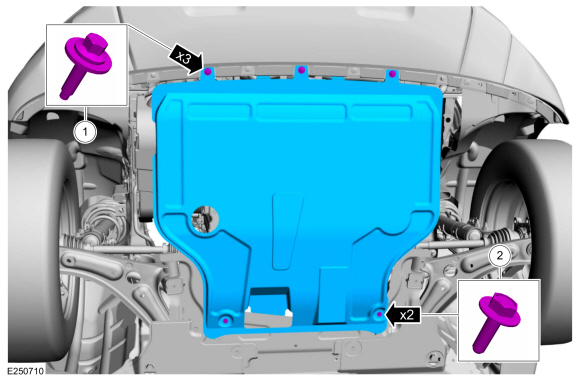
Remove the retainers and the underbody shield.
Torque:
1: 13 lb.in (1.5 Nm)
2: 22 lb.in (2.5 Nm)
 |
-
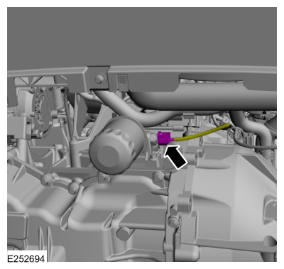
Disconnect the oil pressure switch electrical connector.
 |
-
-
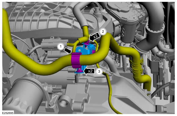
Detach the wiring harness retainer and position the wiring harness aside.
-
Detach the wiring harness retainers and position the wiring harness aside.
-
Remove the starter motor bracket nuts and then remove the starter motor bracket.
Torque: 44 lb.in (5 Nm)
-
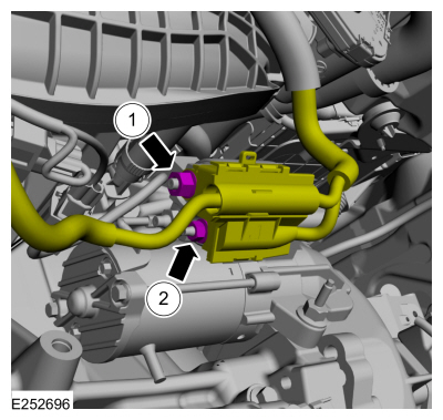
Detach the wiring harness retainer and position the wiring harness aside.
 |
-
-
Remove the starter motor solenoid control wire
retaining nut and then disconnect the starter motor solenoid control
wire.
Torque: 106 lb.in (12 Nm)
-
Remove the starter motor solenoid positive battery
cable retaining nut and then disconnect the starter motor solenoid
battery cable.
Torque: 53 lb.in (6 Nm)
-
Remove the starter motor solenoid control wire
retaining nut and then disconnect the starter motor solenoid control
wire.
 |
-
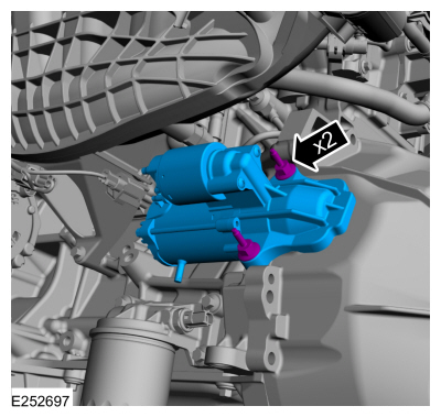
Remove the starter motor retaining bolts and then remove the starter motor.
Torque: 26 lb.ft (35 Nm)
 |
Installation
-
Inspect the starter motor drive gear and ring gear.
Refer to: Starter Motor Drive Gear and Flywheel Ring Gear Inspection (303-06C Starting System - 2.0L Duratec-HE (129kW/175PS), General Procedures).
-
To install, reverse the removal procedure.
 General Procedures - Starter Motor Drive Gear and Flywheel Ring Gear Inspection
Activation
WARNING:
Before beginning any service procedure in this
section, refer to Safety Warnings in section 100-00 General Information...
 Removal and Installation - Start Inhibit Switch
Removal
NOTICE:
Make sure that the clutch pedal remains in the rest position.
NOTE:
Removal steps in this procedure may contain installation details...
Other information:
Ford Ecosport 2014-2025 Service and Repair Manual: Removal and Installation - Electric Booster Heater
Special Tool(s) / General Equipment Interior Trim Remover Removal NOTE: Removal steps in this procedure may installation details. Remove the floor console upper trim panel. Disconnect the electrical connectors...
Ford Ecosport 2014-2025 Service and Repair Manual: General Procedures - Brake Disc Machining
Repair WARNING: Service actions on vehicles equipped with electronic parking brakes may cause unexpected parking brake application, which could result in injury to hands or fingers. Put the electronic parking brake system into service mode prior to servicing or removing rear brake components...
Categories
- Manuals Home
- 2nd Gen Ford Ecosport Service Manual (2014 - 2025)
- Service Information
- General Procedures - Transmission Fluid Level Check
- Removal and Installation - Fuel Pump and Sender Unit
- Description and Operation - Evaporative Emissions - System Operation and Component Description
- Description and Operation - Jacking and Lifting - Overview
Removal and Installation - Steering Column Shaft
Removal
NOTE: Removal steps in this procedure may contain installation details.
NOTICE: Do not allow the steering column to rotate while the steering column shaft is disconnected or damage to the steering column internal sensor may result.
NOTE: Use a steering wheel holding device (such as Hunter® 28-75-1 or equivalent)
Hold the steering wheel in the straight-ahead position.
Copyright © 2025 www.foecosport2.com