Ford Ecosport: Front Suspension / Removal and Installation - Front Stabilizer Bar
Special Tool(s) /
General Equipment
| Tie Rod End Remover |
| Transmission Jack |
Removal
NOTICE:
Suspension fasteners are critical parts that affect the
performance of vital components and systems. Failure of these fasteners
may result in major service expense. Use the same or equivalent parts if
replacement is necessary. Do not use a replacement part of lesser
quality or substitute design. Tighten fasteners as specified.
NOTE:
Removal steps in this procedure may contain installation details.
-
NOTICE:
Disconnect the battery ground cable anytime the
steering gear is being serviced or damage to the steering gear internal
power relay may occur resulting in steering gear replacement.
Disconnect the battery ground cable.
Refer to: Battery Disconnect and Connect (414-01 Battery, Mounting and Cables, General Procedures).
-
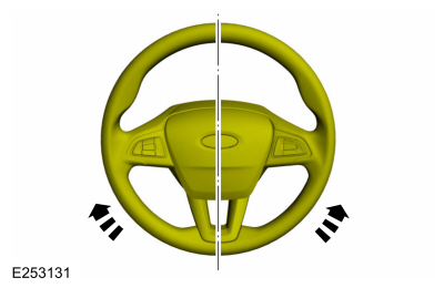
Steering wheel in straight ahead position.
-
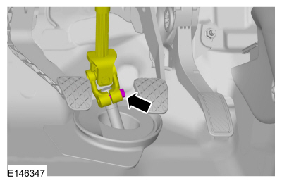
 WARNING:
Do not reuse steering column shaft bolts. This may
result in fastener failure and steering column shaft detachment or loss
of steering control. Failure to follow this instruction may result in
serious injury to vehicle occupant(s).
WARNING:
Do not reuse steering column shaft bolts. This may
result in fastener failure and steering column shaft detachment or loss
of steering control. Failure to follow this instruction may result in
serious injury to vehicle occupant(s).
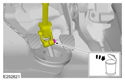
Remove and discard the steering column shaft bolt and
disconnect the steering column shaft from the steering gear.
Torque:
25 lb.ft (34 Nm)
-
Remove the wheel and tire.
Refer to: Wheel and Tire (204-04A Wheels and Tires, Removal and Installation).
-
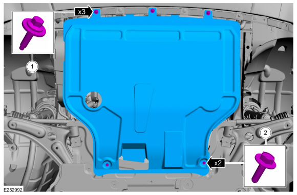
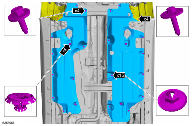
If equipped.
Remove the retainers and the under body shield.
-
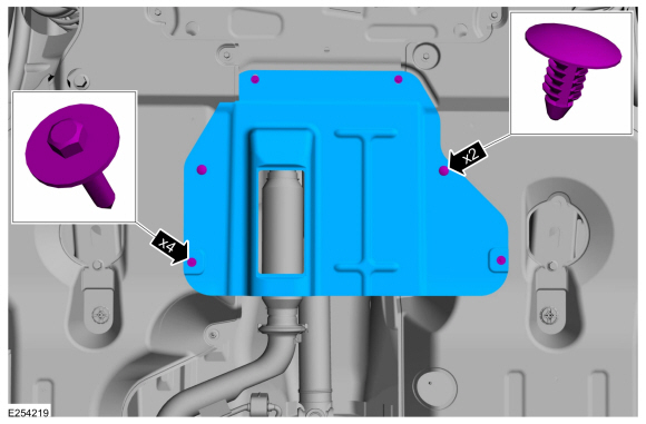
If equipped.
Remove the retainers and the under body air deflector shield.
-
If equipped.
Remove the retainers and the underbody side panels.
-
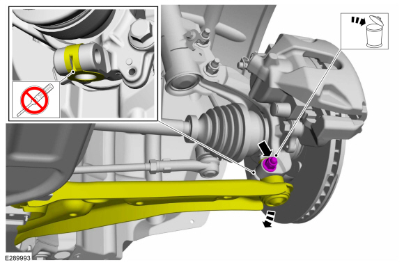
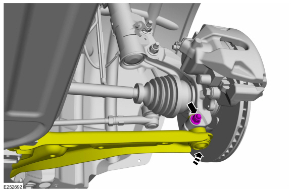
NOTICE:
Do not use a prying device or separator fork between
the ball joint and the wheel knuckle. Damage to the ball joint or ball
joint seal may result. Only use the pry bar by inserting it into the
lower arm body opening.
NOTICE:
Use care when releasing the lower arm and wheel
knuckle into the resting position or damage to the ball joint seal may
occur.
Remove and discard the lower ball joint pinch bolt and nut and separate the ball joint from the wheel knuckle.
-
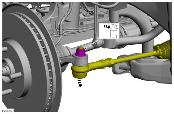
NOTICE:
Do not use a hammer to separate the outer tie-rod
end from the wheel knuckle or damage to the wheel knuckle may result.
NOTICE:
Use care when installing the tie rod separator or damage to the outer tie-rod end boot may occur.
On both sides.
Remove and discard the tie rod end nut and separate the tie rod end from the wheel knuckle.
Use the General Equipment: Tie Rod End Remover
-
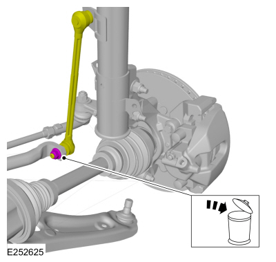
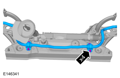
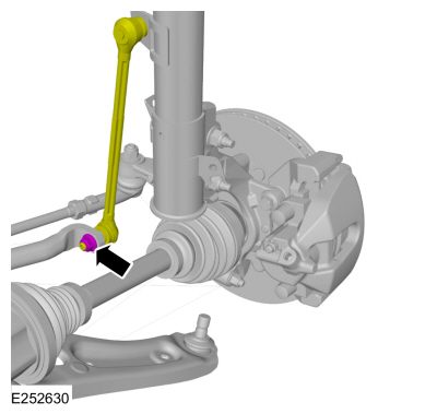
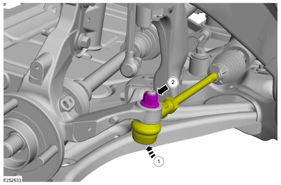
NOTICE:
Make sure that the ball joint ball does not rotate.
NOTE:
The stabilizer bar links are designed with low friction ball joints that have a low breakaway torque.
NOTE:
Use the hex-holding feature to prevent the ball stud
from turning while removing or installing the stabilizer bar link nut.
On both sides.
Remove and discard the stabilizer bar link lower nut and position aside the stabilizer bar link.
-
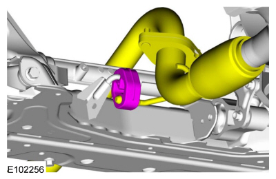
Remove the bolt and position the engine roll restrictor aside.
-
Detach the exhaust hanger isolator.
-
If equipped.
Torque:
35 lb.ft (48 Nm)
-
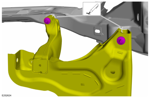
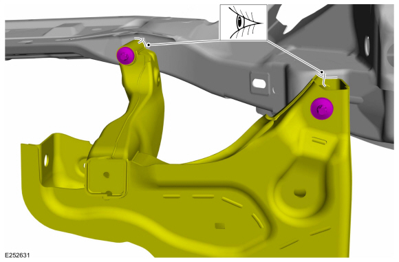
NOTE:
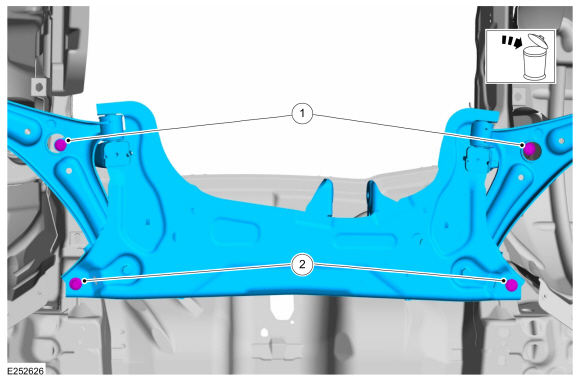
Index mark the subframe positioning for reference during the installation procedure.
On both sides.
Index-mark the subframe to the body.
-
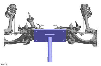
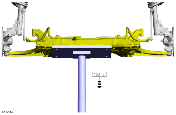
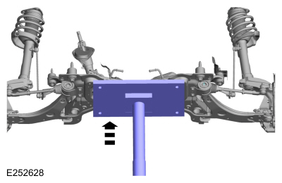
Position a transmission jack under the front subframe.
Use the General Equipment: Transmission Jack
-
-
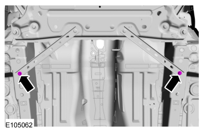
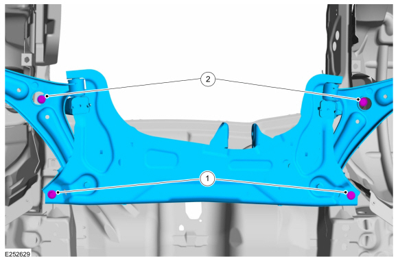
Remove and discard the forward front subframe bolts.
-
Remove and discard the rearward front subframe bolts.
-
Lower the front subframe assembly from the vehicle.
Use the General Equipment: Transmission Jack
-
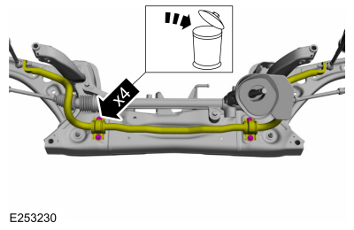
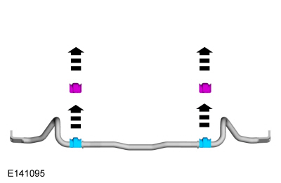
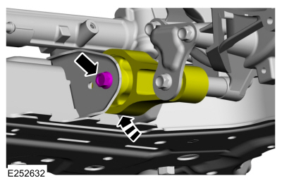
Remove and discard the stabilizer bar bracket bolts.
-
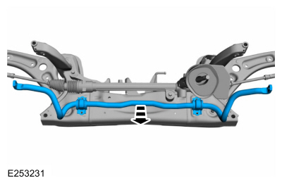
NOTE:
If replacing the stabilizer bar or stabilizer bar
bushings, note the position of the stabilizer bar bushing brackets. The
protrusion on both bushings must be facing the RH side of the vehicle for correct installation.
Remove the front stabilizer bar.
-
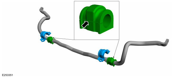
NOTE:
This step is only necessary when installing a new component.
NOTE:
Note the position of each component before removal.
Remove the front stabilizer bar bracket and bush.
Installation
-
To install, reverse the removal procedure.
-
NOTE:
This step is only necessary when installing a new component.
NOTE:
Make sure that the mating faces are clean and free of foreign material.
NOTE:
Make sure that these components are installed to the noted removal position.
On both sides.
Install the front stabilizer bar brackets and bushings.
-
Install the stabilizer bar and new stabilizer bar brackets bolts.
Torque:
35 lb.ft (48 Nm)
-
Partially raise the subframe and position it to the vehicle.
Use the General Equipment: Transmission Jack
-
NOTE:
Do not tighten the bolts at this stage.
-
Install the new rearward front subframe bolts.
-
Install the new forward front subframe bolts.
-
On both sides.
Position the stabilizer bar links and install the new stabilizer bar link lower nut.
Torque:
46 lb.ft (63 Nm)
-
NOTE:
If installing the subframe that was previously removed.
On both sides.
Align the index marks made during removal.
-
-
Tighten the new rearward front subframe bolts.
Torque:
Stage 1:
74 lb.ft (100 Nm)
Stage 2:
240°
-
Tighten the new forward front subframe bolts.
Torque:
Stage 1:
46 lb.ft (63 Nm)
Stage 2:
60°
-
Attach the exhaust hanger isolator.
-
Position the engine roll restrictor and install the engine roll restrictor bolt.
Torque:
59 lb.ft (80 Nm)
-
-
Attach the tie rod to the wheel knuckle.
-
Install the new tie rod nut.
Torque:
39 lb.ft (53 Nm)
-
On both sides.
Connect the lower ball joint to the wheel knuckle and install the new ball joint pinch bolt and nut.
Torque:
38 lb.ft (52 Nm)
-
If removed, install the underbody side panels and the retainers.
Torque:
13 lb.in (1.5 Nm)
-
If removed, install the under body air deflector shield and and the retainers.
-
If removed, install the under body shield and the retainers.
Torque:
1:
13 lb.in (1.5 Nm)
2:
22 lb.in (2.5 Nm)
-
Install the wheels and tires.
Refer to: Wheel and Tire (204-04A Wheels and Tires, Removal and Installation).
-
WARNING:
Do not reuse steering column shaft bolts. This may
result in fastener failure and steering column shaft detachment or loss
of steering control. Failure to follow this instruction may result in
serious injury to vehicle occupant(s).
Position the steering shaft coupler and install the new steering shaft coupler bolt.
Torque:
25 lb.ft (34 Nm)
-
Connect the battery ground cable.
Refer to: Battery Disconnect and Connect (414-01 Battery, Mounting and Cables, General Procedures).
-
Check and if necessary adjust front toe.
Refer to: Front Toe Adjustment (204-00 Suspension System - General Information, General Procedures).
Removal
NOTE:
Removal steps in this procedure may contain installation details.
Remove the cowl panel grille.
Refer to: Cowl Panel Grille (501-02 Front End Body Panels, Removal and Installation)...
Removal
NOTICE:
Suspension fasteners are critical parts that affect the
performance of vital components and systems. Failure of these fasteners
may result in major service expense...
Other information:
Special Tool(s) /
General Equipment
Knife
Removal
NOTE:
Removal steps in this procedure may contain installation details.
Remove the front bumper cover.
Refer to: Front Bumper Cover (501-19 Bumpers, Removal and Installation)...
Materials
Name
Specification
Seam SealerTA-2-B, 3M™ 08308, LORD Fusor® 803DTM
-
Motorcraft® High Performance Engine RTV SiliconeTA-357
WSE-M4G323-A6
Motorcraft® Silicone Spray LubricantXL-6
ESR-M13P4-A
Permatex® Trim and Weatherstrip Adhesive81850
-
..


 Removal and Installation - Front Strut and Spring Assembly
 Removal and Installation - Front Stabilizer Bar Link