Ford Ecosport: Front End Sheet Metal Repairs / Removal and Installation - Dash Panel Crossmember
Special Tool(s) / General Equipment
| 8 mm Drill Bit | |
| MIG/MAG Welding Equipment | |
| Spot Weld Drill Bit | |
| Locking Pliers |
Materials
| Name | Specification |
|---|---|
| Seam Sealer TA-2-B, 3M™ 08308, LORD Fusor® 803DTM |
- |
Removal
NOTE: Factory welds may be substituted with resistance or metal inert gas (MIG) plug welds. Resistance welds may not be placed directly over original location. They must be placed adjacent to original location and match factory welds in quantity. Metal inert gas (MIG) plug welds must equal factory welds in both location and quantity.
NOTE: Adequately protect all adjacent areas against cutting, grinding and welding procedures.
-
Depower the SRS .
Refer to: Supplemental Restraint System (SRS) Repowering (501-20B Supplemental Restraint System, General Procedures).
-
If Required:
Dimensionally restore the vehicle to pre-damage condition.
Refer to: Body and Frame (501-26 Body Repairs - Vehicle Specific Information and Tolerance Checks, Description and Operation).
-
Remove the steering column.
Refer to: Steering Column - LHD (211-04 Steering Column, Removal and Installation).
-
Remove the engine.
Refer to: Engine (303-01A Engine - 1.0L EcoBoost (92kW/125PS), Removal).
Refer to: Engine - 5-Speed Manual Transmission – B5/IB5 (303-01B Engine - 1.5L Duratec (90kW/120PS) – I3, Removal).
Refer to: Engine - 6-Speed Automatic Transmission – 6F15 (303-01B Engine - 1.5L Duratec (90kW/120PS) – I3, Removal).
Refer to: Engine (303-01C Engine - 2.0L Duratec-HE (129kW/175PS), Removal).
-
Remove the hydraulic control unit.
Refer to: Hydraulic Control Unit (HCU) (206-09 Anti-Lock Brake System (ABS) and Stability Control, Removal and Installation).
-
Remove the brake booster.
Refer to: Brake Booster - LHD (206-07 Power Brake Actuation, Removal and Installation).
-
Remove the welds and the dash panel reinforcement.
Use the General Equipment: Spot Weld Drill Bit
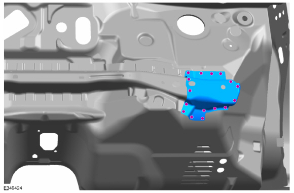 |
-
NOTE: Left hand (LH) side shown, right hand (RH) side similar.
Remove the welds and the dash panel crossmember.
Use the General Equipment: Spot Weld Drill Bit
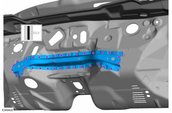 |
Installation
NOTE: Factory welds may be substituted with resistance or metal inert gas (MIG) plug welds. Resistance welds may not be placed directly over original location. They must be placed adjacent to original location and match factory welds in quantity. Metal inert gas (MIG) plug welds must equal factory welds in both location and quantity.
NOTE: Adequately protect all adjacent areas against cutting, grinding and welding procedures.
-
NOTE: Left hand (LH) side shown, right hand (RH) side similar.
Drill plug weld holes in the replacement crossmember.
Use the General Equipment: 8 mm Drill Bit
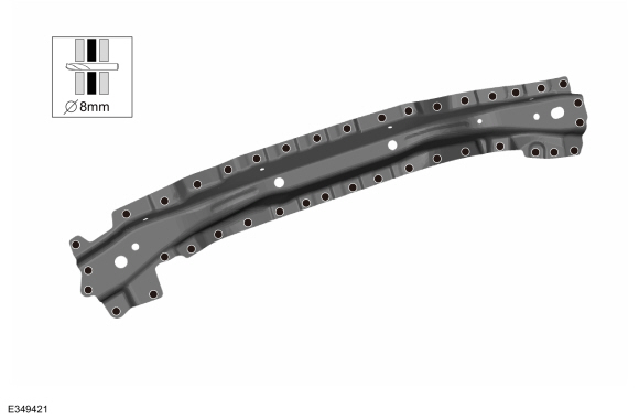 |
-
NOTE: Left hand (LH) side shown, right hand (RH) side similar.
Install, properly position, clamp and weld the replacement crossmember.
Use the General Equipment: Locking Pliers
Use the General Equipment: MIG/MAG Welding Equipment
 |
-
Dress all welds as required using typical metal finishing techniques and materials.
-
Seam Sealing:
All seams must be sealed to production level.
Material: Seam Sealer / TA-2-B, 3M™ 08308, LORD Fusor® 803DTM
 |
-
Drill plug weld holes in the replacement reinforcement dash panel reinforcement.
 |
-
Install,properly position and weld the replacement dash panel reinforcement.
Use the General Equipment: MIG/MAG Welding Equipment
|
-
Dress all welds as required using typical metal finishing techniques.
-
Refinish the entire repair using a Ford approved paint system.
-
If Required:
Restore corrosion protection.
Refer to: Corrosion Prevention (501-25 Body Repairs - General Information, General Procedures).
-
Install the brake booster.
Refer to: Brake Booster - LHD (206-07 Power Brake Actuation, Removal and Installation).
-
Install the hydraulic control unit .
Refer to: Hydraulic Control Unit (HCU) (206-09 Anti-Lock Brake System (ABS) and Stability Control, Removal and Installation).
-
Install the engine.
Refer to: Engine (303-01A Engine - 1.0L EcoBoost (92kW/125PS), Removal).
Refer to: Engine - 5-Speed Manual Transmission – B5/IB5 (303-01B Engine - 1.5L Duratec (90kW/120PS) – I3, Removal).
Refer to: Engine - 6-Speed Automatic Transmission – 6F15 (303-01B Engine - 1.5L Duratec (90kW/120PS) – I3, Installation).
Refer to: Engine (303-01C Engine - 2.0L Duratec-HE (129kW/175PS), Removal).
-
Install the steering column.
Refer to: Steering Column Shaft (211-04 Steering Column, Removal and Installation).
-
Repower the SRS .
Refer to: Supplemental Restraint System (SRS) Repowering (501-20B Supplemental Restraint System, General Procedures).
 Removal and Installation - Dash Panel
Special Tool(s) /
General Equipment
Interior Trim Remover
8 mm Drill Bit
MIG/MAG Welding Equipment
Spot Weld Drill Bit
Locking Pliers
Materials
Name
Specification
Seam SealerTA-2-B, 3M™ 08308, LORD Fusor® 803DTM
-
Removal
NOTE:
Roof removed for clarity...
 Removal and Installation - Fender Apron Panel Reinforcement
Special Tool(s) /
General Equipment
Resistance Spotwelding Equipment
Spherical Cutter
8 mm Drill Bit
MIG/MAG Welding Equipment
Spot Weld Drill Bit
Locking Pliers
Removal
NOTE:
The fender apron panel reinforcement is made of DP600 class
steel and may be sectioned...
Other information:
Ford Ecosport 2014-2025 Service and Repair Manual: Diagnosis and Testing - Fuel Charging
Diagnostic Trouble Code (DTC) Chart Diagnostics in this manual assume a certain skill level and knowledge of Ford-specific diagnostic practices.REFER to: Diagnostic Methods (100-00 General Information, Description and Operation). Module DTC Description Action PCM P0201:00 Cylinder 1 Injector 'A' Circuit/Open: No Sub Type Information GO to Pinpoint Test DI P..
Ford Ecosport 2014-2025 Service and Repair Manual: Removal and Installation - Rocker Panel
Special Tool(s) / General Equipment Resistance Spotwelding Equipment Hot Air Gun Air Body Saw MIG/MAG Welding Equipment Spot Weld Drill Bit Locking Pliers Removal Remove the front door. Refer to: Front Door (501-03 Body Closures, Removal and Installation). Remove the rear door. Refer to: Rear Door (..
Categories
- Manuals Home
- 2nd Gen Ford Ecosport Service Manual (2014 - 2025)
- Removal and Installation - Starter Motor
- Automatic Transmission - 6-Speed Automatic Transmission – 6F35
- Body and Paint
- Removal and Installation - Evaporative Emission Canister Purge Valve
- Removal and Installation - Fuel Pump and Sender Unit
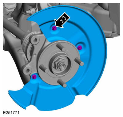
Removal and Installation - Brake Disc Shield
Removal
NOTE: Removal steps in this procedure may contain installation details.
Remove the brake disc.Refer to: Brake Disc (206-03 Front Disc Brake, Removal and Installation).
Remove the bolts and brake disc.
Torque: 80 lb.in (9 Nm)