Ford Ecosport: Fuel Tank and Lines - 2.0L Duratec-HE (129kW/175PS) / Removal and Installation - Fuel Pump and Sender Unit
Special Tool(s) / General Equipment
 |
310-123 Locking Ring, Fuel Tank TKIT-2004J-F TKIT-2005U-LM |
Removal
NOTE: Removal steps in this procedure may contain installation details.
-
Remove the Fuel Tank.
Refer to: Fuel Tank (310-01C Fuel Tank and Lines - 2.0L Duratec-HE (129kW/175PS), Removal and Installation).
-
NOTE: To avoid introducing contamination into the fuel tank use compressed air to clean the Fuel Pump and Sender Unit connections, couplings, flange surfaces and the immediate surrounding area of any dirt or foreign material.
Remove the nuts and remove the fuel pump and sender unit shield.
 |
-
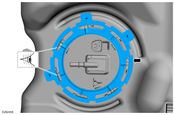
Using the special tool, rotate the lock ring
counter-clockwise and remove the fuel pump and sender unit lock ring.
Use Special Service Tool: 310-123 Locking Ring, Fuel Tank.
 |
-
NOTICE: The Fuel Pump and Sender Unit must be handled carefully to avoid damage to the float arm.
NOTE: Some residual fuel may remain in the Fuel Pump and Sender Unit. Carefully drain into a suitable container.
Carefully lift the fuel pump and sender unit from the fuel tank.
 |
-
Remove and discard the fuel pump and sender unit O-ring seal.
 |
Installation
-
Install the new fuel pump and sender unit O-ring seal.
 |
-
NOTICE: Make sure the alignment locator on the fuel pump and sender unit and the fuel tank meet before tightening the fuel pump and sender unit lock ring.
NOTE: Inspect the mating surfaces of the Fuel Pump and Sender Unit flange and fuel tank O-ring seal contact surfaces. Wipe clean with a lint free towel. Install a new Fuel Pump and Sender Unit or fuel tank if the O-ring seal contact area is bent, scratched or corroded.
Install the fuel pump and sender unit.
 |
-
Tighten the fuel pump and sender unit lock ring until it meets the stop tabs on the fuel tank.
 |
-
Install the fuel pump and sender unit shield and tighten the nuts.
Torque: 80 lb.in (9 Nm)
 |
-
Install the Fuel Tank.
Refer to: Fuel Tank (310-01C Fuel Tank and Lines - 2.0L Duratec-HE (129kW/175PS), Removal and Installation).
 Removal and Installation - Fuel Level Sensor
Removal
NOTE:
Removal steps in this procedure may contain installation details.
Remove the Fuel Pump and Sender Unit.
Refer to: Fuel Pump and Sender Unit (310-01C Fuel Tank and Lines - 2...
 Removal and Installation - Fuel Tank
Special Tool(s) /
General Equipment
Transmission Jack
Retaining Strap
Removal
NOTE:
Removal steps in this procedure may contain installation details...
Other information:
Ford Ecosport 2014-2026 Service and Repair Manual: Removal and Installation - Active Grille Shutter Actuator
Removal NOTE: Removal steps in this procedure may contain installation details. Remove the active grill shutter. Refer to: Active Grille Shutter - 2.0L Duratec-HE (125kW/170PS) – MI4 (501-02 Front End Body Panels, Removal and Installation)...
Ford Ecosport 2014-2026 Service and Repair Manual: Removal and Installation - Audio Unit Antenna Cable
Removal NOTE: Removal steps in this procedure may contain installation details. NOTE: The original equipment audio unit antenna cable is part of the wiring harness and cannot be removed. This procedure refers to replacement of the cable only by overlaying the cable...

