Ford Ecosport: Front End Sheet Metal Repairs / Removal and Installation - Dash Panel
Special Tool(s) / General Equipment
| Interior Trim Remover | |
| 8 mm Drill Bit | |
| MIG/MAG Welding Equipment | |
| Spot Weld Drill Bit | |
| Locking Pliers |
Materials
| Name | Specification |
|---|---|
| Seam Sealer TA-2-B, 3M™ 08308, LORD Fusor® 803DTM |
- |
Removal
NOTE: Roof removed for clarity.
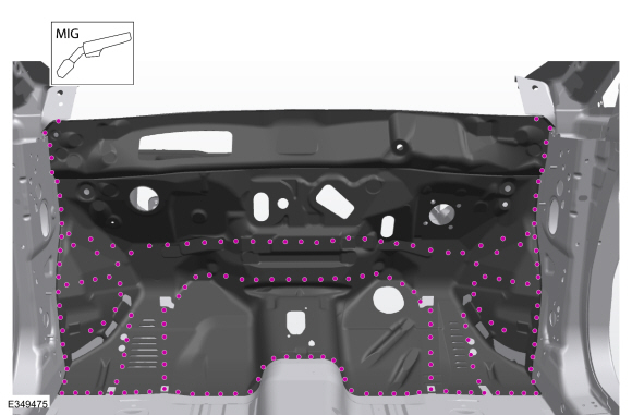
NOTE: Factory welds may be substituted with resistance or metal inert gas (MIG) plug welds. Resistance welds may not be placed directly over original location. They must be placed adjacent to original location and match factory welds in quantity. Metal inert gas (MIG) plug welds must equal factory welds in both location and quantity.
NOTE: Adequately protect all adjacent areas against cutting, grinding and welding procedures.
-
Depower the SRS .
Refer to: Supplemental Restraint System (SRS) Repowering (501-20B Supplemental Restraint System, General Procedures).
-
Remove the windshield glass.
Refer to: Fixed Glass (501-11 Glass, Frames and Mechanisms, General Procedures).
-
If Required:
Dimensionally restore the vehicle to pre-damage condition.
Refer to: Body and Frame (501-26 Body Repairs - Vehicle Specific Information and Tolerance Checks, Description and Operation).
-
On Both Sides:
Remove the front seat.
Refer to: Front Seat Track (501-10A Front Seats, Removal and Installation).
-
On Both Sides:
Remove the A-pillar trim panel.
Refer to: A-Pillar Trim Panel (501-05 Interior Trim and Ornamentation, Removal and Installation).
-
Remove the driver and passenger knee airbag.
Refer to: Driver Knee Airbag (501-20B Supplemental Restraint System, Removal and Installation).
Refer to: Passenger Knee Airbag (501-20B Supplemental Restraint System, Removal and Installation).
-
Remove the steering column.
Refer to: Steering Column - LHD (211-04 Steering Column, Removal and Installation).
-
Remove the instrument panel and console.
Refer to: Floor Console (501-12 Instrument Panel and Console, Removal and Installation).
Refer to: Instrument Panel (501-12 Instrument Panel and Console, Removal and Installation).
-
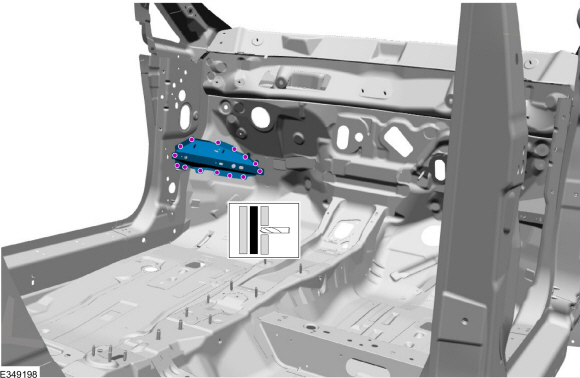
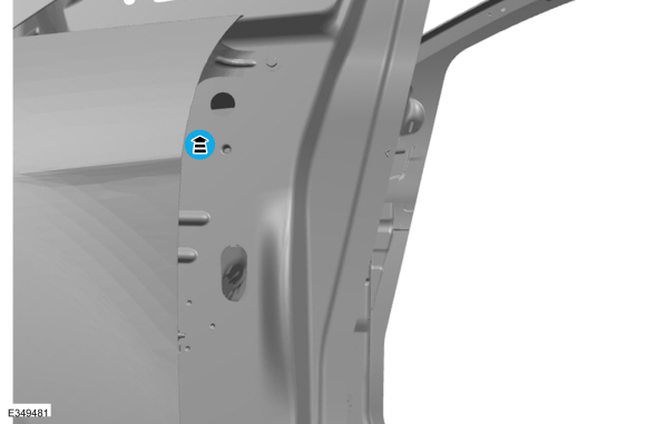
NOTE: Left hand (LH) side shown, right hand (RH) side similar.
On Both Sides:
Remove the welds and the inner dash panel reinforcement.
Use the General Equipment: Spot Weld Drill Bit
 |
-
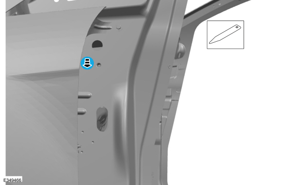
On Both Sides:
Remove the A-pillar to in-vehicle cross beam support bolt cover.
Use the General Equipment: Interior Trim Remover
 |
-
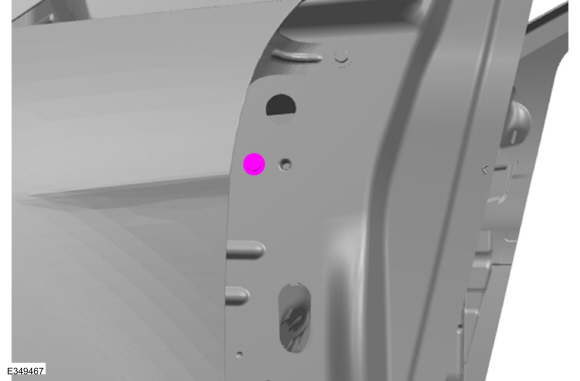
On Both Sides:
Remove the A-pillar to in-vehicle cross beam support bolts and the beam.
 |
-
Remove the climate control housing.
Refer to: Climate Control Housing (412-00 Climate Control System - General Information, Removal and Installation).
-
Remove the hood.
Refer to: Hood (501-02 Front End Body Panels, Removal and Installation).
-
On Both Sides:
Remove the fender and splash shield.
Refer to: Fender (501-02 Front End Body Panels, Removal and Installation).
Refer to: Fender Splash Shield (501-02 Front End Body Panels, Removal and Installation).
-
On Both Sides:
Remove the headlamp assembly.
Refer to: Headlamp Assembly (417-01 Exterior Lighting, Removal and Installation).
-
Remove the front bumper.
Refer to: Front Bumper (501-19 Bumpers, Removal and Installation).
-
If Required:
Remove the engine.
Refer to: Engine (303-01A Engine - 1.0L EcoBoost (92kW/125PS), Removal).
Refer to: Engine - 5-Speed Manual Transmission – B5/IB5 (303-01B Engine - 1.5L Duratec (90kW/120PS) – I3, Removal).
Refer to: Engine - 6-Speed Automatic Transmission – 6F15 (303-01B Engine - 1.5L Duratec (90kW/120PS) – I3, Removal).
Refer to: Engine (303-01C Engine - 2.0L Duratec-HE (129kW/175PS), Removal).
-
Remove the hydraulic control unit.
Refer to: Hydraulic Control Unit (HCU) (206-09 Anti-Lock Brake System (ABS) and Stability Control, Removal and Installation).
-
Remove the brake booster and brake pedal and bracket.
Refer to: Brake Booster - LHD (206-07 Power Brake Actuation, Removal and Installation).
Refer to: Brake Pedal and Bracket (206-06 Hydraulic Brake Actuation, Removal and Installation).
-
Position the carpet, all modules and wiring harnesses away from the working area.
-
Remove the wiper linkage assembly.
Refer to: Wiper Linkage Assembly (501-16 Wipers and Washers, Removal and Installation).
-
Remove the cowl panel.
Refer to: Cowl Panel (501-27 Front End Sheet Metal Repairs, Removal and Installation).
-
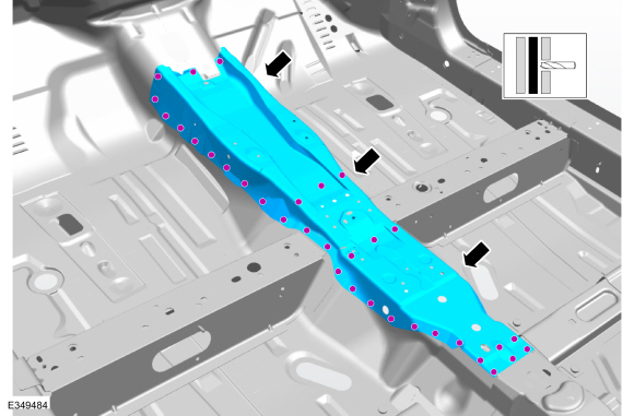
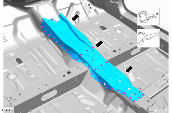
NOTE: Use care during removal the reinforcement is part of the front floor panel and will be reused.
NOTE: Left hand (LH) side shown, right hand (RH) side similar.
Remove the welds and the transmission tunnel reinforcement.
Use the General Equipment: Spot Weld Drill Bit
 |
-
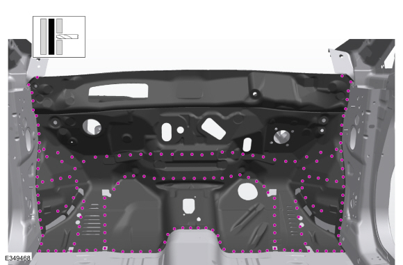
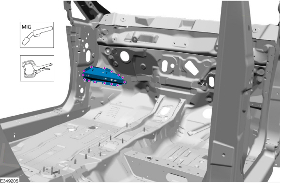
NOTE: Left hand (LH) side shown, right hand (RH) side similar.
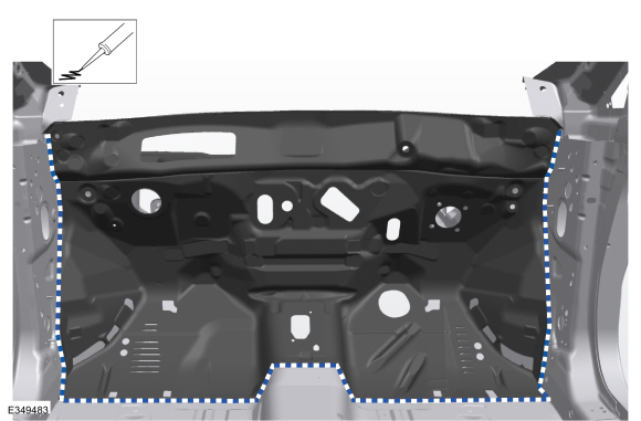
Remove the welds.
Use the General Equipment: Spot Weld Drill Bit
 |
-
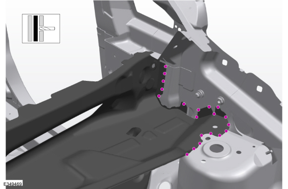
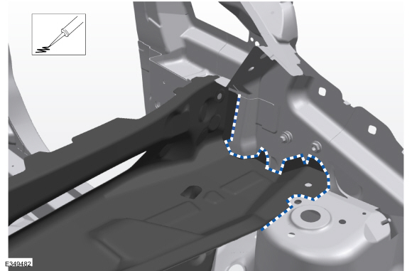
NOTE: Left hand (LH) side shown, right hand (RH) side similar.
On Both Sides:
Remove the welds.
Use the General Equipment: Spot Weld Drill Bit
 |
-
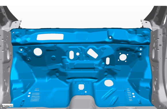
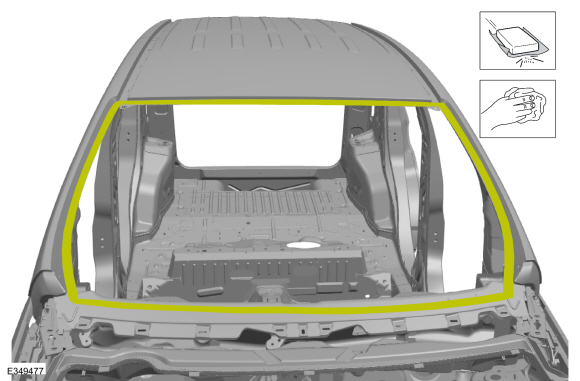
NOTE: Pay particular attention to the location of noise, vibration and harshness (NVH) material, adhesive and sealer used to aid in installation.
Remove the dash panel.
 |
Installation
NOTE: Roof removed for clarity.
NOTE: Factory welds may be substituted with resistance or metal inert gas (MIG) plug welds. Resistance welds may not be placed directly over original location. They must be placed adjacent to original location and match factory welds in quantity. Metal inert gas (MIG) plug welds must equal factory welds in both location and quantity.
NOTE: Adequately protect all adjacent areas against cutting, grinding and welding procedures.
-
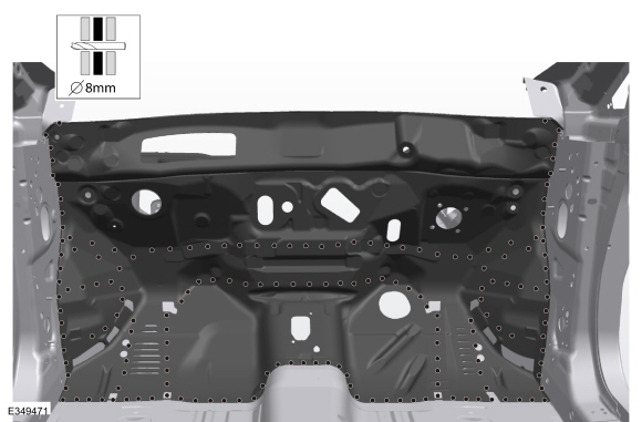
Drill plug weld holes in the replacement dash panel.
Use the General Equipment: 8 mm Drill Bit
 |
-
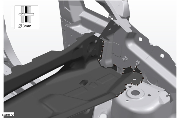
NOTE: Left hand (LH) side shown, right hand (RH) side similar.
On Both Sides:
Drill plug weld holes in the replacement dash panel.
Use the General Equipment: 8 mm Drill Bit
 |
-
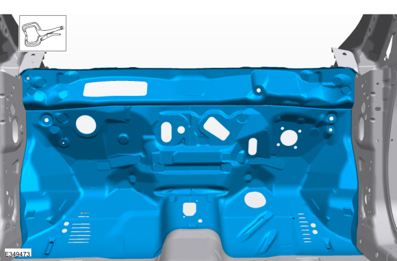
Install, properly position and clamp the replacement dash panel.
Use the General Equipment: Locking Pliers
 |
-
NOTE: Left hand (LH) side shown, right hand (RH) side similar.
On Both Sides:
Install the welds.
Use the General Equipment: MIG/MAG Welding Equipment
 |
-
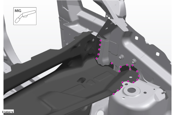
NOTE: Left hand (LH) side shown, right hand (RH) side similar.
On Both Sides:
Install the welds.
Use the General Equipment: MIG/MAG Welding Equipment
 |
-
Dress all welds as required using typical metal finishing techniques and materials.
-
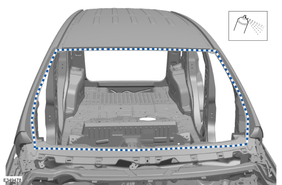
Seam Sealing:
All seams must be sealed to production level.
Material: Seam Sealer / TA-2-B, 3M™ 08308, LORD Fusor® 803DTM
 |
-
Install the transmission tunnel reinforcement, properly position, clamp and install the welds.
Use the General Equipment: Locking Pliers
Use the General Equipment: MIG/MAG Welding Equipment
 |
-
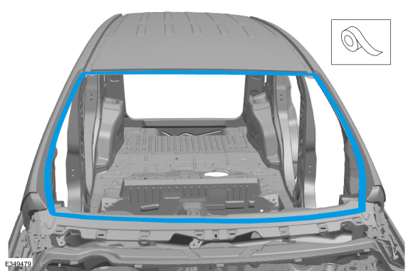
NOTE: Left hand (LH) side shown, right hand (RH) side similar.
On Both Sides:
Apply adhesive.
Material: Seam Sealer / TA-2-B, 3M™ 08308, LORD Fusor® 803DTM
 |
-
Install the cowl panel.
Refer to: Cowl Panel (501-27 Front End Sheet Metal Repairs, Removal and Installation).
-
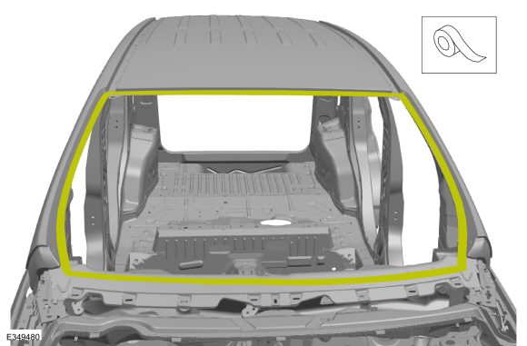
Sand to remove old adhesive, paint, e-coat and clean.
 |
-
Apply a Ford approved epoxy-based primer and allow to dry.
 |
-
Mask off the windshield opening channel.
 |
-
Refinish the entire repair using a Ford approved paint system.
-
Remove the masking material.
 |
-
Obtain a new and install the VIN plate.
Refer to: Identification Codes (100-01 Identification Codes, Description and Operation).
-
Install the windshield glass.
Refer to: Fixed Glass (501-11 Glass, Frames and Mechanisms, General Procedures).
-
Restore corrosion protection.
Refer to: Corrosion Prevention (501-25 Body Repairs - General Information, General Procedures).
-
If Required:
Install the engine.
Refer to: Engine (303-01A Engine - 1.0L EcoBoost (92kW/125PS), Removal).
Refer to: Engine - 5-Speed Manual Transmission – B5/IB5 (303-01B Engine - 1.5L Duratec (90kW/120PS) – I3, Removal).
Refer to: Engine - 6-Speed Automatic Transmission – 6F15 (303-01B Engine - 1.5L Duratec (90kW/120PS) – I3, Removal).
Refer to: Engine (303-01C Engine - 2.0L Duratec-HE (129kW/175PS), Removal).
-
Install the brake booster and brake pedal and bracket.
Refer to: Brake Booster - LHD (206-07 Power Brake Actuation, Removal and Installation).
Refer to: Brake Pedal and Bracket (206-06 Hydraulic Brake Actuation, Removal and Installation).
-
Install the hydraulic control unit.
Refer to: Hydraulic Control Unit (HCU) (206-09 Anti-Lock Brake System (ABS) and Stability Control, Removal and Installation).
-
Reposition all wiring harnesses, modules and the carpet to original locations.
-
Install the wiper linkage assembly.
Refer to: Wiper Linkage Assembly (501-16 Wipers and Washers, Removal and Installation).
-
Install the steering column.
Refer to: Steering Column - LHD (211-04 Steering Column, Removal and Installation).
-
On Both Sides:
Install the in-vehicle cross beam and the A-pillar to cross beam support bolt.
Torque: 26 lb.ft (35 Nm)
|
-
On Both Sides:
Install the A-pillar to in-vehicle cross beam support bolt cover.
 |
-
Install the climate control housing.
Refer to: Climate Control Housing (412-00 Climate Control System - General Information, Removal and Installation).
-
NOTE: Left hand (LH) side shown, right hand (RH) side similar.
On Both Sides:
Install the inner dash panel reinforcemen and the welds.
Use the General Equipment: Locking Pliers
Use the General Equipment: MIG/MAG Welding Equipment
 |
-
Install the instrument panel and console.
Refer to: Instrument Panel (501-12 Instrument Panel and Console, Removal and Installation).
Refer to: Floor Console (501-12 Instrument Panel and Console, Removal and Installation).
-
Install the driver and passenger knee air bag.
Refer to: Driver Knee Airbag (501-20B Supplemental Restraint System, Removal and Installation).
Refer to: Passenger Knee Airbag (501-20B Supplemental Restraint System, Removal and Installation).
-
On Both Sides:
Install the A-pillar trim panel.
Refer to: A-Pillar Trim Panel (501-05 Interior Trim and Ornamentation, Removal and Installation).
-
On Both Sides:
Install the front seat.
Refer to: Front Seat Track (501-10A Front Seats, Removal and Installation).
Refer to: Front Seat (501-10A Front Seats, Removal and Installation).
-
On Both Sides:
Install the fender and splash shield.
Refer to: Fender (501-02 Front End Body Panels, Removal and Installation).
Refer to: Fender Splash Shield (501-02 Front End Body Panels, Removal and Installation).
-
Install the front bumper.
Refer to: Front Bumper (501-19 Bumpers, Removal and Installation).
Refer to: Front Bumper Cover (501-19 Bumpers, Removal and Installation).
-
Install and align the hood.
Refer to: Hood (501-02 Front End Body Panels, Removal and Installation).
Refer to: Hood Alignment (501-03 Body Closures, General Procedures).
-
On Both Sides:
Install the headlamp assembly.
Refer to: Headlamp Assembly (417-01 Exterior Lighting, Removal and Installation).
-
Repower the SRS .
Refer to: Supplemental Restraint System (SRS) Repowering (501-20B Supplemental Restraint System, General Procedures).

 Removal and Installation - Dash Panel Crossmember
Special Tool(s) /
General Equipment
8 mm Drill Bit
MIG/MAG Welding Equipment
Spot Weld Drill Bit
Locking Pliers
Materials
Name
Specification
Seam SealerTA-2-B, 3M™ 08308, LORD Fusor® 803DTM
-
Removal
NOTE:
Factory welds may be substituted with resistance or metal
inert gas (MIG) plug welds...
Other information:
Ford Ecosport 2014-2025 Service and Repair Manual: General Procedures - Seat Heater Mat Removal
Repair WARNING: To minimize the risk of injury, always wear protective gloves when working with a steamer. Failure to follow these instructions may result in serious personal injury. NOTE: Click here to view a video version of the seat heater mat removal and installation...
Ford Ecosport 2014-2025 Service and Repair Manual: Description and Operation - Direct Clutch Assembly
Direct (3, 5, R) Clutch Exploded View Item Description 1 Direct clutch cylinder snap ring 2 Direct clutch cylinder 3 Direct clutch piston 4 Direct clutch piston return spring 5 Direct clutch piston seals 6 ..
Categories
- Manuals Home
- 2nd Gen Ford Ecosport Service Manual (2014 - 2025)
- Diagnosis and Testing - Evaporative Emissions
- General Procedures - Battery Charging
- Removal and Installation - Front Seat
- Climate Control System - General Information
- Removal and Installation - Fuel Pump and Sender Unit
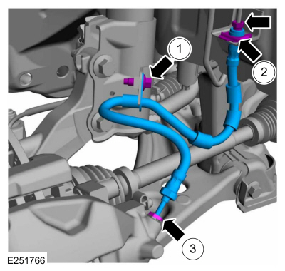
Removal and Installation - Front Brake Flexible Hose
Removal
Remove the wheel and tire.Refer to: Wheel and Tire (204-04A Wheels and Tires, Removal and Installation).
Remove the brake flexible hose bracket bolt.
Disconnect the brake tube fitting and remove the brake hose clip.
Loosen the brake hose fitting and remove the brake flexible hose.