Ford Ecosport: Power Steering / Removal and Installation - Tie Rod
Ford Ecosport 2014-2025 Service and Repair Manual / Steering System / Power Steering / Removal and Installation - Tie Rod
Removal
NOTE: Removal steps in this procedure may contain installation details.
NOTE: If servicing the RH (right-hand) tie rod, both bellows boots must be removed.
-
Remove the steering gear boot.
Refer to: Steering Gear Boot (211-02 Power Steering, Removal and Installation).
-
Position the steering rack far enough to the LH side to expose the flat surface.
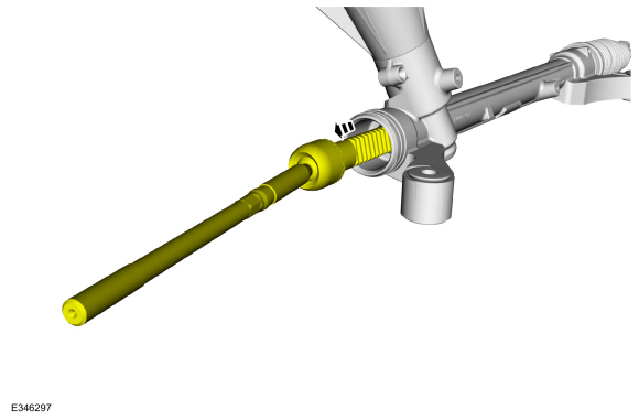 |
-
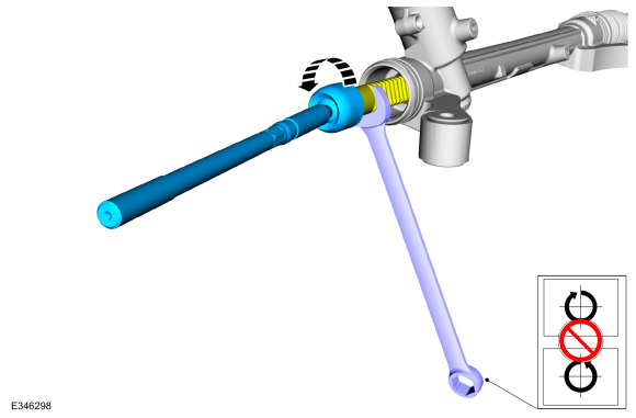
NOTICE: Place the steering gear at the center position and hold the steering gear rack while loosening the tie rod. Use an appropriate-sized wrench on the flat/teeth of the rack to resist rotation and to prevent damage during removal of the tie rod.
NOTE: The steering gear rack can only be held on the LH (left hand) side.
Using an appropriate-sized wrench on the flat/teeth to hold the rack and a commercially available tool such as OTC® Inner Tie Rod Wrench 39E953, remove the tie rod.
Torque: 61 lb.ft (83 Nm)
 |
Installation
-
To install, reverse the removal procedure.
 Removal and Installation - Steering Gear Boot
Special Tool(s) /
General Equipment
204-169Clamping Tool, Boot Retaining Clamp
Removal
NOTE:
Removal steps in this procedure may contain installation details...
 Removal and Installation - Tie Rod End
Special Tool(s) /
General Equipment
211-001
(TOOL-3290-D)
Remover, Tie-Rod End
Removal
NOTE:
Removal steps in this procedure may contain installation details...
Other information:
Ford Ecosport 2014-2025 Service and Repair Manual: Removal and Installation - Steering Column Shrouds
Special Tool(s) / General Equipment Flat-Bladed Screwdriver Interior Trim Remover Removal Lower the steering column adjustment lock. Fully extend and lower the steering column. Release the tabs and disconnect the gap hider from the upper steering column shroud...
Ford Ecosport 2014-2025 Service and Repair Manual: General Procedures - Bezel Diagnostics
Check NOTE: If there is a concern with one of the following components and Bezel Diagnostics cannot be accessed, obtain the module part number or ESN by referencing the label attached to the module. Inoperative ACM Inoperative (blank or does not power on) display unit (non-touchscreen display or touchscreen display) Inoperative FCIM or radio control panel ..
Categories
- Manuals Home
- 2nd Gen Ford Ecosport Service Manual (2014 - 2025)
- General Procedures - Transmission Fluid Level Check
- Description and Operation - Evaporative Emissions - System Operation and Component Description
- Removal and Installation - Fuel Pump and Sender Unit
- Removal and Installation - Evaporative Emission Canister Purge Valve
- Removal and Installation - Starter Motor
Removal and Installation - Oil Pressure Switch
Materials
Name Specification Motorcraft® Thread Sealant with PTFETA-24-B WSK-M2G350-A2
Removal
NOTE: Removal steps in this procedure may contain installation details.
With the vehicle in NEUTRAL, position it on a hoist.Refer to: Jacking and Lifting - Overview (100-02 Jacking and Lifting, Description and Operation).
If equipped, remove the bolts and the underbody shield.
Copyright © 2025 www.foecosport2.com