Ford Ecosport: Engine - 2.0L Duratec-HE (129kW/175PS) / Removal and Installation - Oil Pump
Special Tool(s) /
General Equipment
| Oil Drain Equipment |
| Round-Ended Steel Rule |
Materials
| Name |
Specification |
Motorcraft® Silicone Gasket and Sealant
TA-30 |
WSE-M4G323-A4
|
Removal
NOTICE:
During engine repair procedures, cleanliness is extremely
important. Any foreign material, including any material created while
cleaning gasket surfaces, that enters the oil passages, coolant passages
or the oil pan can cause engine failure.
-
With the vehicle in NEUTRAL, position it on a hoist.
Refer to: Jacking and Lifting - Overview (100-02 Jacking and Lifting, Description and Operation).
-
Remove the engine front cover.
Refer to: Engine Front Cover (303-01C Engine - 2.0L Duratec-HE (129kW/175PS), Removal and Installation).
-
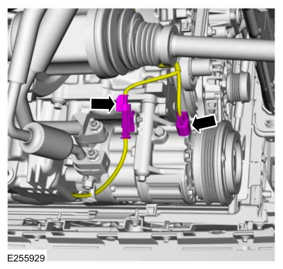
Disconnect the A/C compressor electrical connectors.
-
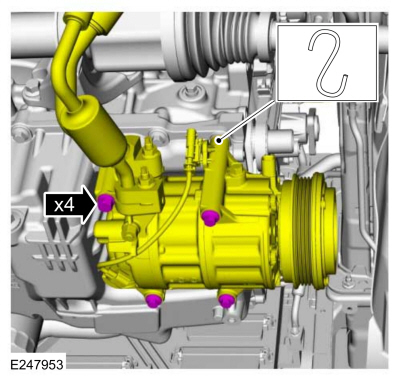
NOTICE:
Support the A/C compressor. Do not allow the A/C compressor to hang by
the A/C lines or damage to the A/C compressor and tubes may occur.
Remove the bolts and position aside the A/C compressor and support.
-
-
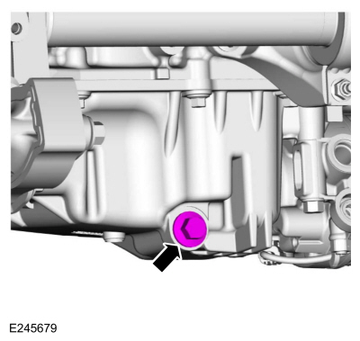
Remove the drain plug and drain the engine oil.
Use the General Equipment: Oil Drain Equipment
-
Install drain plug.
Torque:
20 lb.ft (27 Nm)
-
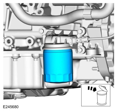
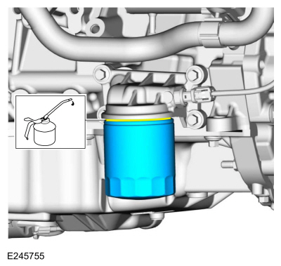
Remove and discard the engine oil filter.
-
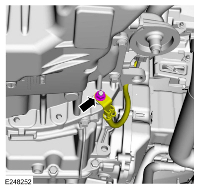
Remove the nut and position the ground cable aside.
-
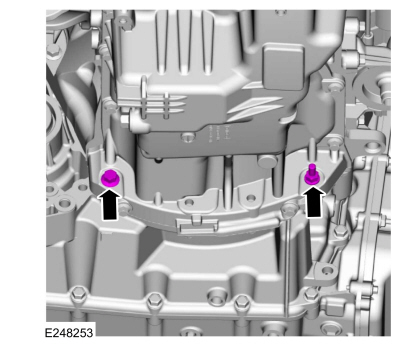
Remove the oil pan bolt and stud bolt.
-
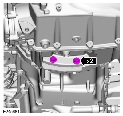
Remove the transmission bolts.
-
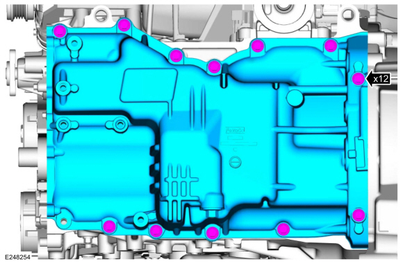
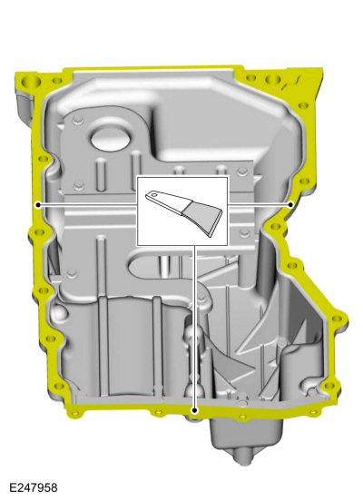
Remove the bolts and the oil pan.
-
Clean and prepare the RTV sealing surface.
Refer to: RTV Sealing Surface Cleaning and Preparation (303-00 Engine System - General Information, General Procedures).
-
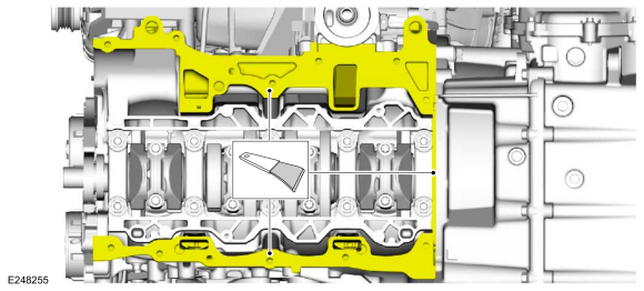
Clean and prepare the RTV sealing surface.
Refer to: RTV Sealing Surface Cleaning and Preparation (303-00 Engine System - General Information, General Procedures).
-
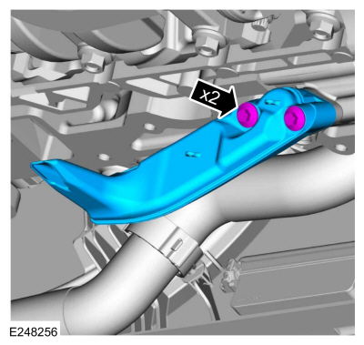
Remove the bolts and the oil pump screen and pickup tube.
-
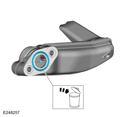
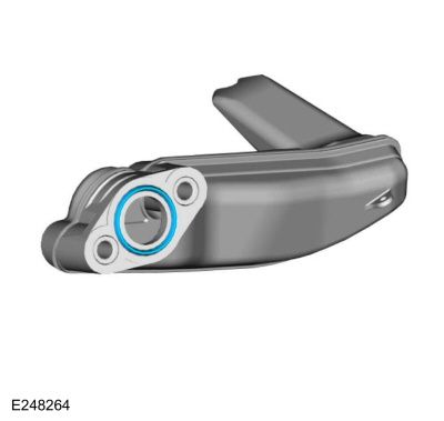
Remove and the discard the O-ring seal.
-
-
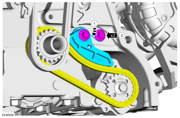
Push the tensioner spring down and release the spring from under the shoulder bolt.
-
Remove the shoulder bolts, tensioner, spring and position the oil pump chain off the oil pump sprocket.
-
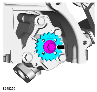
Remove the bolt and oil pump sprocket.
-
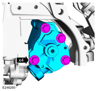
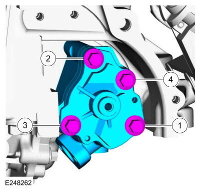
Remove the bolts and the oil pump.
-
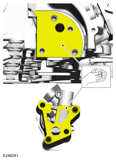
Clean the mating surfaces of the oil pump.
Installation
-
Prime the oil pump. Add 2 tablespoons of clean engine oil to the oil pump and rotate the oil pump by hand.
Refer to: Specifications (303-01C Engine - 2.0L Duratec-HE (129kW/175PS), Specifications).
-
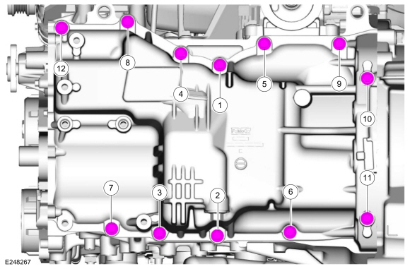
Install the oil pump and tighten the bolts in sequence shown in 2 stages.
Torque:
Stage 1:
89 lb.in (10 Nm)
Stage 2:
177 lb.in (20 Nm)
-
Install the oil pump sprocket and bolt.
Torque:
18 lb.ft (25 Nm)
-
-
Position the oil pump chain on the oil pump sprocket
and install the tensioner, spring and the shoulder bolts.
Torque:
89 lb.in (10 Nm)
-
Push the tensioner spring down and position the spring under the shoulder bolt.
-
Install a new O-ring seal.
-
Install the oil pump screen and pickup tube and the bolts.
Torque:
89 lb.in (10 Nm)
-
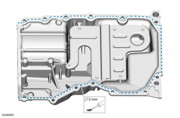
NOTE:
If the oil pan is not secured within 10 minutes of
sealant application, the sealant must be removed and the sealing area
cleaned with metal surface prep. Allow to dry until there is no sign of
wetness, or 10 minutes, whichever is longer. Failure to follow this
procedure can cause future oil leakage.
Apply a 3 mm (0.19 in) bead of silicone sealant.
Material: Motorcraft® Silicone Gasket and Sealant
/ TA-30
(WSE-M4G323-A4)
-
NOTE:
Do not tighten the oil pan bolts at this time.
Install the oil pan and the bolts finger-tight.
-
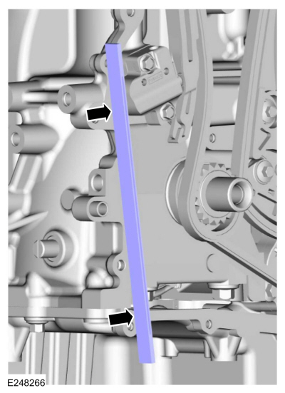
Align the front surface of the oil pan flush with the front surface of the engine block.
Use the General Equipment: Round-Ended Steel Rule
-
Tighten the oil pan bolts in sequence shown.
Torque:
18 lb.ft (25 Nm)
-
Install the transmission bolts.
Torque:
35 lb.ft (48 Nm)
-
Install the oil pan bolt and stud bolt.
Torque:
35 lb.ft (48 Nm)
-
Position the ground cable and install the nut.
Torque:
177 lb.in (20 Nm)
-
NOTE:
Lubricate the engine oil filter gasket with clean engine oil prior to installing the oil filter.
Install a new engine oil filter.
Torque:
Stage 1:
71 lb.in (8 Nm)
Stage 2:
180°
-
Remove the support and position the A/C compressor and install the bolts.
Torque:
18 lb.ft (25 Nm)
-
Connect the A/C compressor electrical connectors.
-
Install the engine front cover.
Refer to: Engine Front Cover (303-01C Engine - 2.0L Duratec-HE (129kW/175PS), Removal and Installation).
-
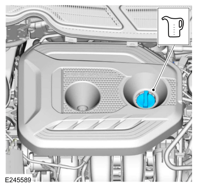
Fill the engine with clean engine oil.
Refer to: Specifications (303-01C Engine - 2.0L Duratec-HE (129kW/175PS), Specifications).
Materials
Name
Specification
Motorcraft® Thread Sealant with PTFETA-24-B
WSK-M2G350-A2
Removal
NOTE:
Removal steps in this procedure may contain installation details...
Special Tool(s) /
General Equipment
303-1565Alignment Tool, CamshaftTKIT-2010C-FLM
Removal
NOTICE:
Do not loosen or remove the crankshaft pulley bolt without
first installing the special tools as instructed in this procedure...
Other information:
Overview
BLIS ®
The BLIS
® aids the driver in assessing whether another vehicle is present
within a specific area (blind spot) to either side of the vehicle,
extending rearward approximately 4 m (13 ft) beyond the rear bumper
while driving on roads and highways...
Removal
NOTICE:
Do not press, pull or otherwise move the brake pedal
while installing the stoplamp switch and cruise control deactivation
switch. Install these switches with the booster push rod attached to the
brake pedal and with the brake pedal in the at-rest position...

 Removal and Installation - Oil Pressure Switch
 Removal and Installation - Timing Chain