Ford Ecosport: Engine - 2.0L Duratec-HE (129kW/175PS) / Removal and Installation - Timing Chain
Special Tool(s) / General Equipment
 |
303-1565 Alignment Tool, Camshaft TKIT-2010C-FLM |
Removal
NOTICE: Do not loosen or remove the crankshaft pulley bolt without first installing the special tools as instructed in this procedure. The crankshaft pulley and the crankshaft timing sprocket are not keyed to the crankshaft. The crankshaft, the crankshaft sprocket and the pulley are fitted together by friction. For that reason, the crankshaft sprocket is also unfastened if the pulley bolt is loosened. Before any repair requiring loosening or removal of the crankshaft pulley bolt, the crankshaft and camshafts must be locked in place by the special service tools, otherwise severe engine damage can occur.
NOTICE: During engine repair procedures, cleanliness is extremely important. Any foreign material, including any material created while cleaning gasket surfaces, that enters the oil passages, coolant passages or the oil pan can cause engine failure.
NOTE: If it is necessary to install a new timing chain tensioner, a cast iron tensioner is to be replaced with an aluminum tensioner (6K254). The existing bolts must be discarded and replaced with new bolts (6K282).
-
With the vehicle in NEUTRAL, position it on a hoist.
Refer to: Jacking and Lifting - Overview (100-02 Jacking and Lifting, Description and Operation).
-
Remove the following items:
-
Remove the high-pressure fuel pump drive unit.
Refer to: High-Pressure Fuel Pump Drive Unit (303-04C Fuel Charging and Controls - 2.0L Duratec-HE (129kW/175PS), Removal and Installation).
-
Remove the engine front cover.
Refer to: Engine Front Cover (303-01C Engine - 2.0L Duratec-HE (129kW/175PS), Removal and Installation).
-
Remove the high-pressure fuel pump drive unit.
-
NOTICE: The Camshaft Alignment Tool is for camshaft alignment only. Do not rely on the Camshaft Alignment Tool to prevent camshaft rotation. Damage to the tool or the camshaft can occur.
Install the special tool into the slots on the back of the camshafts.
Install Special Service Tool: 303-1565 Alignment Tool, Camshaft.
 |
-
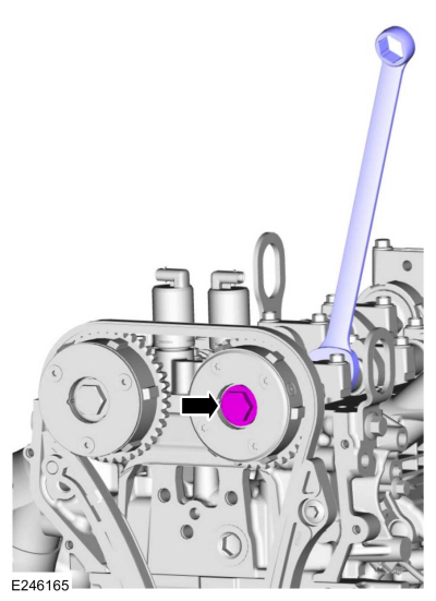
NOTICE: Use an open-ended wrench to prevent the component from turning.
Loosen the exhaust VCT unit bolt.
 |
-
NOTICE: Use an open-ended wrench to prevent the component from turning.
Loosen the intake VCT unit bolt.
 |
-
NOTE: If equipped with cast iron timing chain tensioner.
-
Using a small pick, release and hold the ratchet mechanism.
-
While holding the ratchet mechanism in the released
position, compress the tensioner by pushing the timing chain arm toward
the tensioner.
-
Insert a holding pin into the hole to retain the tensioner.
-
Using a small pick, release and hold the ratchet mechanism.
 |
-
NOTE: If it is necessary to install a new timing chain tensioner, a cast iron tensioner is to be replaced with an aluminum tensioner (6K254). The existing bolts must be discarded and replaced with new bolts (6K282).
NOTE: If equipped with cast iron timing chain tensioner.
Remove the bolts and the timing chain tensioner.
 |
-
NOTE: If equipped with aluminum timing chain tensioner.
Remove the bolts and the timing chain tensioner.
 |
-
-
Remove the timing chain tensioner arm.
-
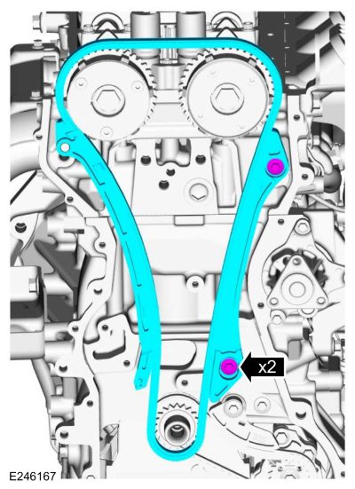
Remove the timing chain.
-
Remove the bolts and the timing chain guide.
-
Remove the timing chain tensioner arm.
 |
-
-
Remove the bolts and VCT units.
-
Discard the bolts.
-
Remove the bolts and VCT units.
 |
Installation
-
NOTE: Do not tighten the bolts at this time. The bolts will be tightened during the timing chain installation procedure.
Install the VCT units and the new bolts finger tight.
 |
-
-
Install the timing chain guide and the bolts.
Torque: 89 lb.in (10 Nm)
-
Install the timing chain.
-
Install the timing chain tensioner arm.
-
Install the timing chain guide and the bolts.
|
NOTE: If equipped with aluminum timing chain tensioner.
NOTE: If the timing chain tensioner plunger is not pinned in the compressed position, follow the next step.
-
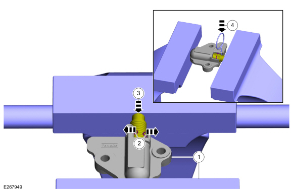
Reset the timing chain tensioner.
-
Position the timing chain tensioner in a soft-jawed vise.
-
Spread the ends of the ratchet wire clip apart.
-
Using the soft-jawed vise, compress the plunger to the reset position.
-
Install a locking pin in the 2 holes of the timing chain tensioner body to hold the plunger in place.
-
Position the timing chain tensioner in a soft-jawed vise.
 |
-
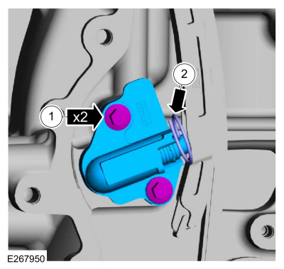
NOTE: If equipped with aluminum timing chain tensioner.
NOTE: Do not remove the locking pin until the tensioner bolts are tightened.
-
Install the timing chain tensioner and the bolts.
Torque: 89 lb.in (10 Nm)
-
Remove the locking pin.
-
Install the timing chain tensioner and the bolts.
 |
NOTE: If equipped with cast iron timing chain tensioner.
NOTE: If the timing chain tensioner plunger and ratchet assembly are not pinned in the compressed position, follow the next 4 steps.
-
NOTICE: Do not compress the ratchet assembly. This will damage the ratchet assembly.
Using the edge of a vise, compress the timing chain tensioner plunger.
 |
-
Using a small pick, push back and hold the ratchet mechanism.
 |
-
While holding the ratchet mechanism, push the ratchet arm back into the tensioner housing.
 |
-
Install a locking pin into the hole in the tensioner
housing to hold the ratchet assembly and the plunger in during
installation.
 |
-
NOTE: If equipped with cast iron timing chain tensioner.
NOTE: Do not remove the locking pin until the tensioner bolts are tightened.
Install the timing chain tensioner and the bolts.
Torque: 89 lb.in (10 Nm)
|
-
NOTE: If equipped with cast iron timing chain tensioner.
Remove the locking pin.
 |
-
NOTICE: Use an open-ended wrench to prevent the component from turning.
Tighten the exhaust VCT unit bolt.
Torque:
Stage 1: 44 lb.ft (60 Nm)
Stage 2: 90°
|
-
NOTICE: Use an open-ended wrench to prevent the component from turning.
Tighten the intake VCT unit bolt.
Torque:
Stage 1: 44 lb.ft (60 Nm)
Stage 2: 90°
|
- Remove Special Service Tool: 303-1565 Alignment Tool, Camshaft.
|
-
Install the following items:
-
Install the engine front cover.
Refer to: Engine Front Cover (303-01C Engine - 2.0L Duratec-HE (129kW/175PS), Removal and Installation).
-
Install the high-pressure fuel pump drive unit.
Refer to: High-Pressure Fuel Pump Drive Unit (303-04C Fuel Charging and Controls - 2.0L Duratec-HE (129kW/175PS), Removal and Installation).
-
Install the engine front cover.
 Removal and Installation - Oil Pump
Special Tool(s) /
General Equipment
Oil Drain Equipment
Round-Ended Steel Rule
Materials
Name
Specification
Motorcraft® Silicone Gasket and SealantTA-30
WSE-M4G323-A4
Removal
NOTICE:
During engine repair procedures, cleanliness is extremely
important...
 Removal and Installation - Valve Cover
Special Tool(s) /
General Equipment
205-153
(T80T-4000-W)
Handle
303-1247VCT Spark Plug Tube Seal Remover and InstallerTKIT-2006UF-FLMTKIT-2006UF-ROW
Plastic Scraper
Materials
Name
Specification
Motorcraft® Silicone Gasket and SealantTA-30
WSE-M4G323-A4
Removal
NOTICE:
During engine repair procedures, cleanli..
Other information:
Ford Ecosport 2014-2026 Service and Repair Manual: Diagnosis and Testing - Pinpoint Test - DTC: C, Vehicles With: Rear Seat Side Airbag
B0004:11, B0004:12, B0004:13, B0004:1A Refer to Wiring Diagrams Cell 46 for schematic and connector information. Normal Operation and Fault Conditions The RCM continuously monitors the driver knee airbag circuits for the following faults: Resistance out of range Unexpected voltage Short to ground Faulted driver knee airbag If a fault is de..
Ford Ecosport 2014-2026 Service and Repair Manual: General Procedures - Supplemental Restraint System (SRS) Repowering
Repower WARNING: Incorrect repair techniques or actions can cause an accidental Supplemental Restraint System (SRS) deployment. Never compromise or depart from these instructions. Failure to precisely follow all instructions could result in serious personal injury from an accidental deployment. NOTE: The SRS must be fully operational and free of faults before releas..
Categories
- Manuals Home
- 2nd Gen Ford Ecosport Service Manual (2014 - 2026)
- General Procedures - Battery Charging
- Removal and Installation - Front Seat
- Removal and Installation - Roof Rail
- Diagnosis and Testing - Evaporative Emissions
- Removal and Installation - Blower Motor
Disassembly - Engine
Special Tool(s) / General Equipment
 205-153
(T80T-4000-W)
205-153
(T80T-4000-W)
Handle
 303-103
(T74P-6375-A)
303-103
(T74P-6375-A)
Holding Tool, Flywheel
T74P-77000-A
TKIT-2009TC-F
 303-1247
VCT Spark Plug Tube Seal Remover and Installer
TKIT-2006UF-FLM
TKIT-2006UF-ROW
 303-15