Ford Ecosport: Multifunction Electronic Modules / Removal and Installation - Body Control Module (BCM)
Removal
NOTE: Removal steps in this procedure may contain installation details.
-
NOTE: If installing a new module, it is necessary to upload the module configuration information to the diagnostic scan tool prior to removing the module. This information must be downloaded into the new module after installation.
Carry out the PMI procedure for the BCM .
Refer to: Module Programming (418-01 Module Configuration, General Procedures).
-
Remove the battery energy control module B.
Refer to: Battery Energy Control Module B (BECMB) (501-20B Supplemental Restraint System, Removal and Installation).
-
Remove the hush panel.
Remove the bolts and detach the RH hush panel out of the BCM lower bracket.
-
Disconnect the electrical connector.
-
Disconnect the electrical connector.
 |
-
Remove the glove compartment tray and disconnect the electrical connector.
 |
-
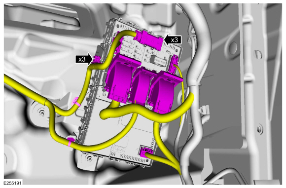
Detach the wiring retainers and disconnect the electrical connectors.
 |
-
NOTICE: Make sure that the BCM is removed together with the bracket to prevent damage to the BCM .
Remove the retainers and the BCM and bracket.
 |
-
Release the tab and slide the BCM off the bracket.
 |
Installation
-
To install, reverse the removal procedure.
NOTE: Carry out the remaining steps only if installing a new BCM .
-
NOTE: The PMI (programmable module installation) application in the scan tool will guide you through completing the BCM (body control module) programming and key programming.
Run the PMI on the BCM .
-
After keys have been programmed as directed by the on screen prompts,
and the BCM programming has fully completed (as indicated by a module
installation complete or successful message), carry out the PATS Module
Initialization using the FDRS Scan Tool PATS Application.
-
As directed by the scan tool, follow the onscreen promts to relearn the TPMS sensors.
Refer to: Tire Pressure Monitoring System (TPMS) Sensor Location Calibration (204-04B Tire Pressure Monitoring System (TPMS), General Procedures).
-
If equipped with a video rear parking aid (rear mounted only), using a
diagnostic scan tool, carry out the LIN New Module Initialization
function.
-
Using a diagnostic scan tool, carry out the BMS Learned Values Reset.
-
Configure the BCM Programmable Parameters.
Refer to: Module Programming (418-01 Module Configuration, General Procedures).
-
Using a diagnostic scan tool, carry out the BCM self-test (must include
an on-demand self-test) and then repeat the self-test to confirm all
DTC have been cleared.
-
NOTE: This step only applies to vehicles without a stand-alone PAM (parking assist control module).
Using a diagnostic scan tool, complete the PMI process for the PAM following the on-screen instructions.
Refer to: Module Configuration - System Operation and Component Description (418-01 Module Configuration, Description and Operation).
 General Procedures - Transport Mode Deactivation
Deactivation
NOTE:
After vehicle build, some vehicle modules are set in Transport mode
including the IPC and the BCM . Transport mode reduces battery drain
during longer periods where the vehicle is not used...
 Removal and Installation - Driver Door Module (DDM)
Removal
NOTE:
Removal steps in this procedure may contain installation details.
NOTE:
If installing a new module, it is necessary to
upload the module configuration information to the diagnostic scan tool
prior to removing the module...
Other information:
Ford Ecosport 2014-2026 Service and Repair Manual: General Procedures - Parking Brake Cable Adjustment - Vehicles With: Rear Drum Brakes
Special Tool(s) / General Equipment 206-D002 (D81L-1103-A) Gauge, Brake Adjustment Cable Ties Adjustment NOTE: LHD shown, RHD similar. Detach the parking brake control boot and position the boot upward on the handle...
Ford Ecosport 2014-2026 Service and Repair Manual: General Procedures - Heater Core Leak Check - Vehicles With: R1234YF Refrigerant
Inspection NOTE: A coolant leak in the heater hose could follow the heater core tube to the heater core and appear as a leak in the heater core. Inspect for evidence of coolant leakage at the heater hose to heater core attachments...
Categories
- Manuals Home
- 2nd Gen Ford Ecosport Service Manual (2014 - 2026)
- Automatic Transmission - 6-Speed Automatic Transmission – 6F35
- Removal and Installation - Front Seat
- Removal and Installation - Blower Motor
- Body and Paint
- General Procedures - Transmission Fluid Level Check
Description and Operation - Health and Safety Precautions
General Service Warnings
Review carefully the information below before beginning any repair. Following these warnings is a list of specific system warnings that must be reviewed before beginning work on any listed system.
 WARNING:
Wear eye and ear protection when servicing a vehicle.
Failure to follow this instruction may result in serious personal
injury.
WARNING:
Wear eye and ear protection when servicing a vehicle.
Failure to follow this instruction may result in serious personal
injury.