Ford Ecosport: Fuel Charging and Controls - 2.0L Duratec-HE (129kW/175PS) / Removal and Installation - High-Pressure Fuel Pump
Removal
NOTICE: Do not loosen any fittings or plugs on the high-pressure fuel pump.
-
Release the fuel system pressure.
Refer to: Fuel System Pressure Release (310-00C Fuel System - General Information - 2.0L Duratec-HE (129kW/175PS), General Procedures).
-
Remove the intake manifold.
Refer to: Intake Manifold (303-01C Engine - 2.0L Duratec-HE (129kW/175PS), Removal and Installation).
-
Remove the air cleaner outlet pipe.
Refer to: Air Cleaner Outlet Pipe (303-12C Intake Air Distribution and Filtering - 2.0L Duratec-HE (129kW/175PS), Removal and Installation).
-
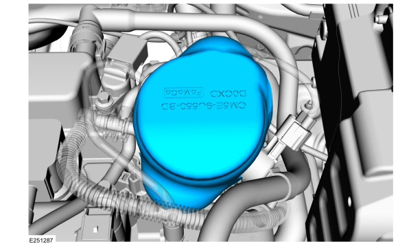
NOTE: When removing or installing the fuel injection pump noise insulator, spreading the openings will reduce the risk of damage.
Remove the fuel injection pump noise insulator.
 |
-
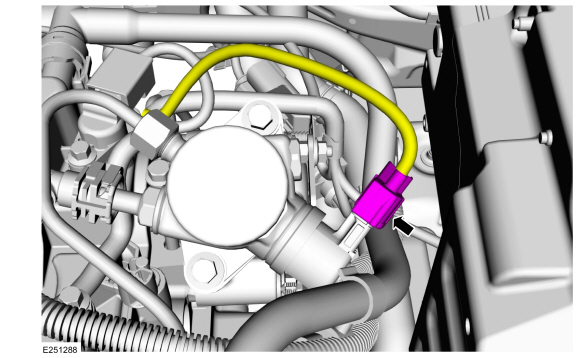
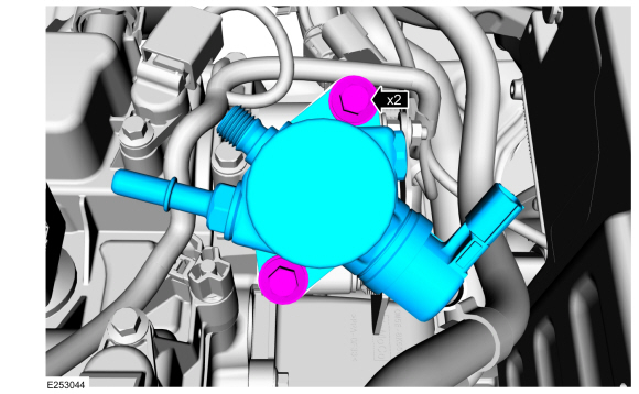
Disconnect the fuel pump electrical connector.
 |
-
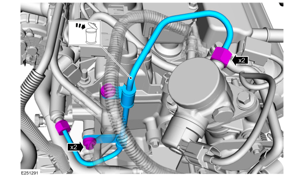
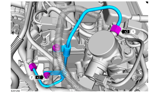
NOTICE: To release the fuel pressure in the high pressure fuel tube, wrap the fuel injection pump flare nut with a shop towel to absorb any residual fuel pressure during the loosening of fuel injection pump flare nut.
Remove the high pressure fuel tube bracket bolts. Loosen the high pressure fuel tube flare nuts, then remove and discard the high pressure fuel tube.
 |
-
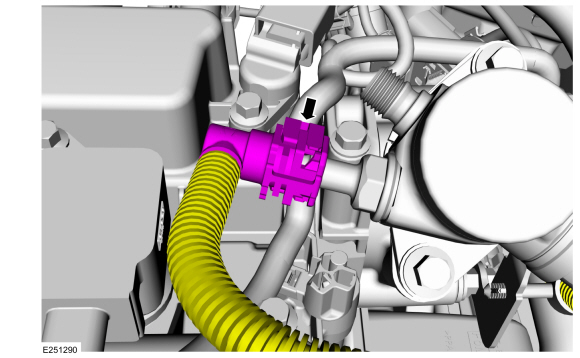
Disconnect the high-pressure fuel pump quick release coupling.
Refer to: Quick Release Coupling (310-00 Fuel System - General Information - 2.0L Duratec-HE (129kW/175PS), 2.0L Duratec-HE (125kW/170PS) - MI4, 2.0L Duratec-HE Flex Fuel (129kW/175PS)) .
 |
-
NOTE: Alternately loosen the high-pressure fuel pump bolts one complete revolution at a time.
-
Remove the high-pressure fuel pump bolts.
-
Remove the high-pressure fuel pump.
-
Remove the high-pressure fuel pump bolts.
 |
-
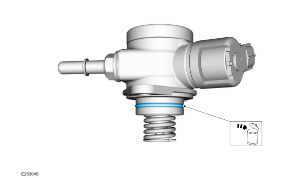
Remove and discard the high-pressure fuel pump O-ring seal.
 |
-
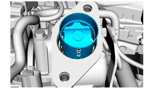
Remove the high-pressure fuel pump tappet.
 |
Installation
-
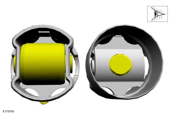
Inspect the high-pressure fuel pump tappet. If any flat
spots or scoring are found, especially in the indicated areas, then
inspect the high-pressure fuel pump and the high-pressure fuel pump
tappet drive lobe. Install new components as needed.
 |
-
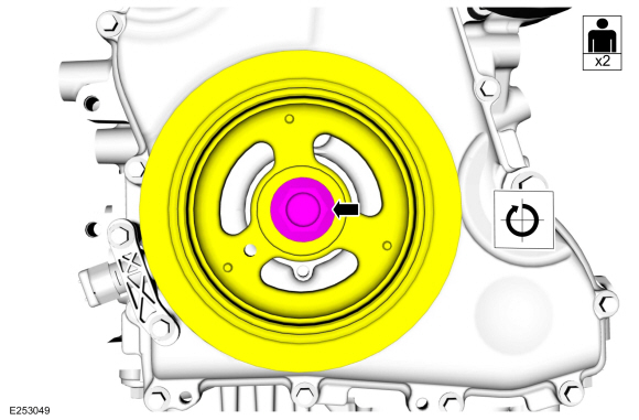
NOTICE: Only rotate the crankshaft Clockwise (CW) or damage to the engine may occur.
With the help of an assistant, using the crankshaft pulley bolt, turn the crankshaft Clockwise (CW) until the high-pressure fuel pump cam lobe is at BDC .
 |
-
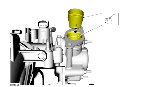
NOTE: Align the notch on the high-pressure fuel pump tappet with the groove in the high-pressure fuel pump drive unit bore.
Apply clean engine oil to the high-pressure fuel pump drive unit bore and the drive lobe and the high-pressure fuel pump tappet. Install the high-pressure fuel pump tappet.
Refer to: Specifications (303-01C Engine - 2.0L Duratec-HE (129kW/175PS), Specifications).
 |
-
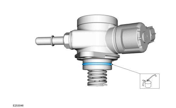
Install a new high-pressure fuel pump O-ring seal. Lubricate the new O-ring seal with clean engine oil.
Refer to: Specifications (303-01C Engine - 2.0L Duratec-HE (129kW/175PS), Specifications).
 |
-
Install the high-pressure fuel pump and the
high-pressure fuel pump bolts. Alternately tighten each bolt 1/2 of a
turn until seated and then tighten in the following 2 stages.
Torque:
Stage 1: Tighten first to: : 177 lb.in (20 Nm)
Stage 2: Tighten an additional: : 45°
|
-
Connect the high-pressure fuel pump quick release coupling.
Refer to: Quick Release Coupling (310-00 Fuel System - General Information - 2.0L Duratec-HE (129kW/175PS), 2.0L Duratec-HE (125kW/170PS) - MI4, 2.0L Duratec-HE Flex Fuel (129kW/175PS)) .
|
-
NOTE: Calculate the correct torque wrench setting for the following torque using the Torque Wrench Adapter Formulas.
Position a new high-pressure fuel tube and hand start the flare nuts. Loosely install the high pressure fuel tube bracket bolts.
-
Tighten the high pressure fuel tube flare nuts in the following 2 stages.
Torque:
Stage 1: Tighten the high pressure fuel tube flare nuts first to: : 89 lb.in (10 Nm)
Stage 2: Tighten an additional: : 30°
-
Tighten the high-pressure fuel tube bracket bolts.
Torque: 89 lb.in (10 Nm)
-
Tighten the high pressure fuel tube flare nuts in the following 2 stages.
 |
-
Connect the fuel pump electrical connector.
|
-
NOTE: When removing or installing the fuel injection pump noise insulator, spreading the openings will reduce the risk of damage.
Install the fuel injection pump noise insulator.
|
-
Install the air cleaner outlet pipe.
Refer to: Air Cleaner Outlet Pipe (303-12C Intake Air Distribution and Filtering - 2.0L Duratec-HE (129kW/175PS), Removal and Installation).
-
Install the intake manifold.
Refer to: Intake Manifold (303-01C Engine - 2.0L Duratec-HE (129kW/175PS), Removal and Installation).
-
Pressurize the fuel system.
Refer to: Fuel System Pressure Release (310-00C Fuel System - General Information - 2.0L Duratec-HE (129kW/175PS), General Procedures).
 Removal and Installation - Fuel Rail
Special Tool(s) /
General Equipment
303-1567Sizer, Teflon SealTKIT-2010C-FLM
307-005
(T59L-100-B)
Slide Hammer
310-205Fuel Injector Brush
310-206Remover, Fuel InjectorTKIT-2009A-FLM
310-207Installer, Fuel Injector Seal AssemblyTKIT-2009A-FLM
Removal
Release the fuel system pressure...
 Removal and Installation - High-Pressure Fuel Pump Drive Unit
Removal
Remove the high-pressure fuel pump.
Refer to: High-Pressure Fuel Pump (303-04C Fuel Charging and Controls -
2.0L Duratec-HE (129kW/175PS), Removal and Installation)...
Other information:
Ford Ecosport 2014-2025 Service and Repair Manual: Removal and Installation - Fender Apron Panel Reinforcement
Special Tool(s) / General Equipment Resistance Spotwelding Equipment Spherical Cutter 8 mm Drill Bit MIG/MAG Welding Equipment Spot Weld Drill Bit Locking Pliers Removal NOTE: The fender apron panel reinforcement is made of DP600 class steel and may be sectioned...
Ford Ecosport 2014-2025 Service and Repair Manual: Removal and Installation - Rear Wheelhouse Outer
Special Tool(s) / General Equipment Spherical Cutter Air Body Saw MIG/MAG Welding Equipment Locking Pliers Materials Name Specification Seam SealerTA-2-B, 3M™ 08308, LORD Fusor® 803DTM - Removal NOTE: LH side shown, RH side similar...
Categories
- Manuals Home
- 2nd Gen Ford Ecosport Service Manual (2014 - 2025)
- Climate Control System - General Information
- Automatic Transmission - 6-Speed Automatic Transmission – 6F35
- Diagnosis and Testing - Body Control Module (BCM)
- General Procedures - Transmission Fluid Level Check
- Removal and Installation - Starter Motor
Removal and Installation - Oil Pressure Switch
Materials
Name Specification Motorcraft® Thread Sealant with PTFETA-24-B WSK-M2G350-A2
Removal
NOTE: Removal steps in this procedure may contain installation details.
With the vehicle in NEUTRAL, position it on a hoist.Refer to: Jacking and Lifting - Overview (100-02 Jacking and Lifting, Description and Operation).
If equipped, remove the bolts and the underbody shield.