Ford Ecosport: Engine - 2.0L Duratec-HE (129kW/175PS) / General Procedures - Valve Clearance Adjustment
Special Tool(s) / General Equipment
| Feeler Gauge |
Check
-
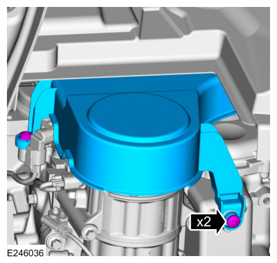
Remove the valve cover.
Refer to: Valve Cover (303-01C Engine - 2.0L Duratec-HE (129kW/175PS), Removal and Installation).
-
Remove the RH front wheel and tire.
Refer to: Wheel and Tire (204-04A Wheels and Tires, Removal and Installation).
-
Remove the fasteners and the accessory drive belt cover.
 |
-
NOTE: Turn the engine clockwise only, and only use the crankshaft bolt.
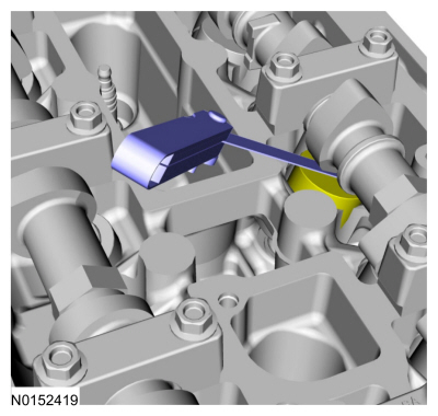
NOTE: Measure the clearance of each valve at base circle, with the lobe pointed away from the tappet.
Use a feeler gauge to measure the clearance of each valve and record its location.
Use the General Equipment: Feeler Gauge
 |
-
NOTE: The number on the valve tappet only reflects the digits that follow the decimal. For example, a tappet with the number 0.650 has the thickness of 3.650 mm.
NOTE: Select tappets using this formula: tappet thickness = measured clearance + the existing tappet thickness - nominal clearance.
NOTE: The nominal clearance is:
- intake: 0.25 mm (0.0095 in).
- exhaust: 0.36 mm (0.0142 in).
NOTE: The acceptable clearances after being fully installed are:
- intake: 0.19-0.31 mm (0.007-0.012 in).
- exhaust: 0.30-0.42 mm (0.012-0.017 in).
-
If any tappets do not measure within specifications, install new tappets in those locations.
Adjustment
-
NOTE: The following step is only necessary if adjustment is required.
Remove the camshafts.
Refer to: Camshaft (303-01C Engine - 2.0L Duratec-HE (129kW/175PS), Removal and Installation).

 Removal and Installation - Camshaft
Special Tool(s) /
General Equipment
303-1565Alignment Tool, CamshaftTKIT-2010C-FLM
303-507Timing Peg, Crankshaft TDCTKIT-2001N-FLMTKIT-2001N-ROW
Feeler Gauge
Materials
Name
Specification
Flange SealantCU7Z-19B508-A
WSS-M2G348-A11
Removal
NOTICE:
During engine repair procedures, cleanliness is extremely
important..
Other information:
Ford Ecosport 2014-2025 Service and Repair Manual: Diagnosis and Testing - Horn
DTC Chart Diagnostics in this manual assume a certain skill level and knowledge of Ford-specific diagnostic practices. REFER to: Diagnostic Methods (100-00 General Information, Description and Operation). BCM DTC Chart DTC Description Actions B1323:11 Horn Switch: Circuit S..
Ford Ecosport 2014-2025 Service and Repair Manual: Removal and Installation - Rear Door Check Arm
Removal NOTE: Removal steps in this procedure may contain installation details. NOTE: LH side shown, RH side similar. Open the rear door. Remove the check arm bolt. Torque: 17 lb.ft (23 Nm) Remove the rear door trim panel. Refer to: Rear Door Trim Panel (501-..
Categories
- Manuals Home
- 2nd Gen Ford Ecosport Service Manual (2014 - 2025)
- Diagnosis and Testing - Body Control Module (BCM)
- Diagnosis and Testing - Evaporative Emissions
- Removal and Installation - Fuel Pump and Sender Unit
- Removal and Installation - Body Control Module (BCM)
- Removal and Installation - Block Heater
Description and Operation - Health and Safety Precautions
General Service Warnings
Review carefully the information below before beginning any repair. Following these warnings is a list of specific system warnings that must be reviewed before beginning work on any listed system.
 WARNING:
Wear eye and ear protection when servicing a vehicle.
Failure to follow this instruction may result in serious personal
injury.
WARNING:
Wear eye and ear protection when servicing a vehicle.
Failure to follow this instruction may result in serious personal
injury.