Ford Ecosport: Engine - 2.0L Duratec-HE (129kW/175PS) / Removal and Installation - Camshaft
Special Tool(s) / General Equipment
 |
303-1565 Alignment Tool, Camshaft TKIT-2010C-FLM |
 |
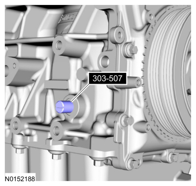
303-507 Timing Peg, Crankshaft TDC TKIT-2001N-FLM TKIT-2001N-ROW |
| Feeler Gauge | |
Materials
| Name | Specification |
|---|---|
| Flange Sealant CU7Z-19B508-A |
WSS-M2G348-A11 |
Removal
NOTICE: During engine repair procedures, cleanliness is extremely important. Any foreign material (including any material created while cleaning gasket surfaces) that enters the oil passages, coolant passages or the oil pan can cause engine failure.
NOTICE: Do not rotate the camshafts unless instructed to in this procedure. Rotating the camshafts or crankshaft with timing components loosened or removed can cause serious damage to the valves and pistons.
NOTICE: Failure to position the No. 1 piston at TDC can result in damage to the engine. Turn the engine in the normal direction of rotation only.
NOTICE: The Camshaft Alignment Tool is for camshaft alignment only. Using this tool to prevent engine rotation can result in engine damage.
NOTE: The Crankshaft TDC Timing Peg will contact the crankshaft and prevent it from turning past TDC . However, the crankshaft can still be rotated in the counterclockwise direction. The crankshaft must remain at the TDC position during the camshaft removal and installation
-
With the vehicle in NEUTRAL, position it on a hoist.
Refer to: Jacking and Lifting - Overview (100-02 Jacking and Lifting, Description and Operation).
-
Release the fuel system pressure.
Refer to: Fuel System Pressure Release (310-00C Fuel System - General Information - 2.0L Duratec-HE (129kW/175PS), General Procedures).
-
Remove the VCT unit.
Refer to: Variable Camshaft Timing (VCT) Unit (303-01C Engine - 2.0L Duratec-HE (129kW/175PS), Removal and Installation).
-
NOTICE: The Camshaft Alignment Tool is for camshaft alignment only. Using this tool to prevent engine rotation can result in engine damage.
Remove Special Service Tool: 303-1565 Alignment Tool, Camshaft.
 |
-
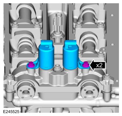
Remove the bolts and the VCT oil control solenoids.
 |
-
Remove the bolts and the front camshaft cap.
 |
-
NOTICE: Failure to follow the camshaft bearing cap loosening procedure can result in damage to the camshafts.
NOTE: Note the location and orientation of each camshaft bearing cap and the position of the camshaft lobes on the No. 1 cylinder for installation reference.
NOTE: Inspect the camshaft bores for any scratches that can be felt by hand.
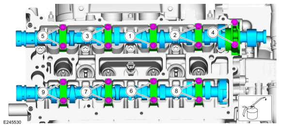
Loosen the camshaft bearing caps in sequence 2 turns at a time until all tension is released from the camshaft bearing caps and remove the bolts, caps and camshafts.
 |
-
Clean the rear camshaft cap.
 |
Installation
-
NOTICE: If any new parts are being installed (cylinder head, valves, tappets, camshafts) it is necessary to check the valve clearance, follow the next 14 steps exactly or serious damage to the engine may occur. If the original parts are being installed it is not necessary to check the valve clearance so proceed to step 15.
Install the crankshaft bolt, washer and place a paint mark on the crankshaft bolt at the 12 o'clock position.
 |
- Remove Special Service Tool: 303-507 Timing Peg, Crankshaft TDC.
 |
-
NOTE: Rotating the crankshaft will position all of the pistons below the deck of the cylinder block and allow the camshafts to be installed and the valve clearance checked without the possibility of damage to the valves or pistons.
Using the crankshaft bolt and washer, rotate the crankshaft clockwise 270 degrees until the paint mark is at the 9 o'clock position.
 |
-
NOTICE: Failure to follow the camshaft tightening procedure can result in damage to the camshafts.
-
Lubricate the camshafts, camshaft journals and camshaft bearing caps with clean engine oil and install.
-
Install the camshaft caps and the bolts.
-
Tighten 2 turns at a time in the sequence shown in 2 stages.
Torque:
Stage 1: 62 lb.in (7 Nm)
Stage 2: 142 lb.in (16 Nm)
-
Lubricate the camshafts, camshaft journals and camshaft bearing caps with clean engine oil and install.
 |
-
Lubricate the camshafts journals with clean engine oil and install the camshaft cap and the bolts.
Torque:
Stage 1: 62 lb.in (7 Nm)
Stage 2: 142 lb.in (16 Nm)
 |
-
NOTICE: Do not remove the spark plugs when the engine is hot or cold soaked. Spark plug thread or cylinder head damage can occur. Make sure the engine is warm (hand touch after cooling down) prior to spark plug removal.
NOTICE: If a spark plug is dropped, internal damage may result and the spark plug must be discarded. The use of a damaged spark plug may cause cylinder misfire resulting in engine damage.
NOTE: Only use hand tool to remove the spark plugs.
Remove the spark plugs.
 |
-
-
Using the flats of the camshaft, rotate the camshaft
to place the cam lobe at base circle, with the lobe pointed away from
the tappet.
-
Use a feeler gauge to measure the clearance of each valve and record its location.
Use the General Equipment: Feeler Gauge
-
Repeat to measure all of the lobe/tappet clearances.
-
Using the flats of the camshaft, rotate the camshaft
to place the cam lobe at base circle, with the lobe pointed away from
the tappet.
 |
-
NOTE: The number on the valve tappet only reflects the digits that follow the decimal. For example, a tappet with the number 0.650 has the thickness of 3.650 mm.
NOTE: Select tappets using this formula: tappet thickness = measured clearance + the existing tappet thickness - nominal clearance.
NOTE: The nominal clearance is:
- intake: 0.25 mm (0.0095 in).
- exhaust: 0.36 mm (0.0142 in).
NOTE: The acceptable clearances after being fully installed are:
- intake: 0.19-0.31 mm (0.007-0.012 in).
- exhaust: 0.30-0.42 mm (0.012-0.017 in).
-
NOTE: Only use hand tool to install the spark plugs.
Install the spark plugs.
Torque: 133 lb.in (15 Nm)
|
-
Remove the bolts and the front camshaft cap.
|
-
NOTICE: Failure to follow the camshaft loosening procedure can result in damage to the camshafts.
Loosen the camshaft bearing caps in sequence 2 turns at a time until all tension is released from the camshaft bearing caps and remove the bolts, caps and camshafts.
|
-
- Install Special Service Tool: 303-507 Timing Peg, Crankshaft TDC.
 |
-
NOTE: Rotating the crankshaft will position the engine at TDC and allow you to install the camshafts in the same position as noted during the disassembly.
Rotate the crankshaft clockwise 90 degrees so the crankshaft contacts the crankshaft timing peg.
 |
-
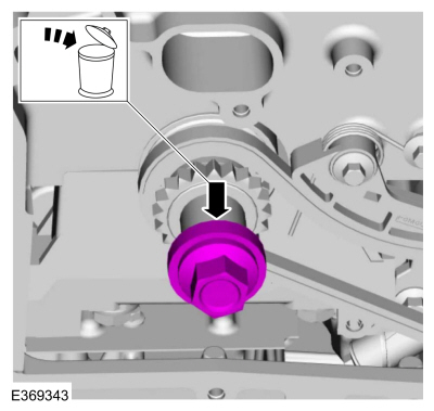
Remove the crankshaft pulley bolt and discard.
 |
-
NOTE: Lubricate the valve tappets with clean engine oil.
If necessary, replace any tappets with the correct tappets selected during the valve clearance check.
 |
-
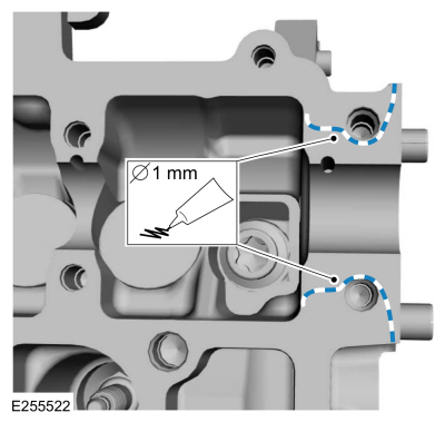
NOTE: The exhaust camshaft rear bearing cap must be secured within 10 minutes of gasket maker application. If the bearing cap is not secured within 10 minutes, the gasket maker must be removed and the sealing area cleaned.
NOTE: Do not allow sealant to enter the camshaft bearing journal. If gasket maker is applied to the camshaft bearing journal, the journal and sealing area must be cleaned.
Apply 1 mm (0.039 in) beads of flange sealant as shown.
Material: Flange Sealant / CU7Z-19B508-A (WSS-M2G348-A11)
 |
-
NOTICE: Install the camshafts with the alignment slots in the camshafts lined up so the Camshaft Alignment Plate can be installed without rotating the camshafts. Make sure the lobes on the No. 1 cylinder are in the same position as noted in the removal procedure. Rotating the camshafts when the timing chain is removed, or installing the camshafts 180 degrees out of position can cause severe damage to the valves and pistons.
NOTICE: Failure to follow the camshaft tightening procedure can result in damage to the camshafts.
NOTICE: Wipe off any excess sealer from the fuel injection pump housing sealing surface of the cylinder head and rear camshaft cap.
NOTE: Lubricate the camshaft, camshaft journals and camshaft bearing caps with clean engine oil.
Install the camshafts, caps, bolts and tighten the camshaft bearing cap bolts one turn at a time, until finger-tight.
Torque:
Stage 1: 62 lb.in (7 Nm)
Stage 2: 142 lb.in (16 Nm)
|
-
Lubricate the camshafts journals with clean engine oil and install the camshaft cap and the bolts.
Torque:
Stage 1: 62 lb.in (7 Nm)
Stage 2: 142 lb.in (16 Nm)
|
-
Install the VCT oil control solenoids and the bolts.
Torque: 89 lb.in (10 Nm)
|
-
NOTICE: The Camshaft Alignment Tool is for camshaft alignment only. Using this tool to prevent engine rotation can result in engine damage.
Install the special tool into the slots on the back of the camshafts.
Install Special Service Tool: 303-1565 Alignment Tool, Camshaft.
|
-
Install the VCT units.
Refer to: Variable Camshaft Timing (VCT) Unit (303-01C Engine - 2.0L Duratec-HE (129kW/175PS), Removal and Installation).
 General Procedures - Valve Clearance Adjustment
Special Tool(s) /
General Equipment
Feeler Gauge
Check
Remove the valve cover.
Refer to: Valve Cover (303-01C Engine - 2...
 Removal and Installation - Crankshaft Front Seal
Special Tool(s) /
General Equipment
303-096
(T74P-6150-A)
Installer, Camshaft Front Oil SealTKIT-2009TC-F
303-409
(T92C-6700-CH)
Remover, Crankshaft SealTKIT-1992-FH/FMH/FLMHTKIT-1993-LMH/MH
Removal
NOTICE:
Do not loosen or remove the crankshaft pulley bolt without
first installing the special tools as instructed in this procedure...
Other information:
Ford Ecosport 2014-2025 Service and Repair Manual: Removal and Installation - Roof Rail
Special Tool(s) / General Equipment Interior Trim Remover Removal NOTE: Removal steps in this procedure may contain installation details. NOTE: LH side shown, RH side similar. If equipped. Rotate the cross member retainer nut counter clockwise and remove the retainer nut...
Ford Ecosport 2014-2025 Service and Repair Manual: Removal and Installation - Horn
Removal NOTE: Removal steps in this procedure may contain installation details. NOTE: LH horn shown, RH horn similar. Remove the headlamp assembly. Disconnect the electrical connector and detach the wiring retainer...
Categories
- Manuals Home
- 2nd Gen Ford Ecosport Service Manual (2014 - 2025)
- Diagnosis and Testing - Body Control Module (BCM)
- Description and Operation - Evaporative Emissions - System Operation and Component Description
- Removal and Installation - Evaporative Emission Canister Purge Valve
- Diagnosis and Testing - Evaporative Emissions
- Removal and Installation - Roof Rail
Removal and Installation - Oil Pressure Switch
Materials
Name Specification Motorcraft® Thread Sealant with PTFETA-24-B WSK-M2G350-A2
Removal
NOTE: Removal steps in this procedure may contain installation details.
With the vehicle in NEUTRAL, position it on a hoist.Refer to: Jacking and Lifting - Overview (100-02 Jacking and Lifting, Description and Operation).
If equipped, remove the bolts and the underbody shield.