Ford Ecosport: Horn / Diagnosis and Testing - Horn
DTC Chart
Diagnostics in this manual assume a certain skill level and knowledge of Ford-specific diagnostic practices.
REFER to: Diagnostic Methods (100-00 General Information, Description and Operation).
BCM DTC Chart
| DTC | Description | Actions |
|---|---|---|
| B1323:11 | Horn Switch: Circuit Short To Ground | GO to Pinpoint Test C |
| B1C55:12 | Horn Relay: Circuit Short to Battery | GO to Pinpoint Test C |
| B1C55:14 | Horn Relay: Circuit Short to Ground or Open |
|
Symptom Chart(s)
Symptom Chart:
Diagnostics in this manual assume a certain skill level and knowledge of Ford-specific diagnostic practices.
REFER to: Diagnostic Methods (100-00 General Information, Description and Operation).
| Condition | Possible Sources | Actions |
| Both horns are inoperative |
|
|
| An individual horn is inoperative |
|
|
| The horns are always on |
|
|
Pinpoint Tests
|
Refer to Wiring Diagrams Cell 44 for schematic and connector information. Normal Operation and Fault Conditions
REFER to: Horn - Overview (413-06 Horn, Description and Operation). DTC Fault Trigger Conditions
Possible Sources
Visual Inspection and Pre-checks
NOTICE: Use the correct probe adapter(s) when making measurements. Failure to use the correct probe adapter(s) may damage the connector. NOTICE: The following pinpoint test uses a test lamp to simulate normal circuit loads. Use only a Rotunda Test Lamp (SGT27000) or 250-300mA incandescent bulb test lamp. To avoid connector terminal damage, use the Rotunda Flex Probe kit for the test lamp probe connection to the vehicle. Do not use the test lamp probe directly on any connector. |
|||||||||||||
| A1 CHECK THE BCM (BODY CONTROL MODULE) OUTPUT BY ACTIVATING THE BCM (BODY CONTROL MODULE) HORN_RELAY PID (PARAMETER IDENTIFICATION) | |||||||||||||
Do the horns sound when commanded ON?
|
|||||||||||||
| A2 CHECK THE HORN RELAY | |||||||||||||
Did the horn relay pass the component test?
|
|||||||||||||
| A3 CHECK THE HORN RELAY VOLTAGE SUPPLY CIRCUITS FOR AN OPEN | |||||||||||||
Does the test lamp illuminate when connected?
|
|||||||||||||
| A4 CHECK THE HORN RELAY OUTPUT | |||||||||||||
Do the horns sound when the jumper wire is connected?
|
|||||||||||||
| A5 CHECK THE HORN VOLTAGE CIRCUIT FOR AN OPEN | |||||||||||||
Is the resistance less than 3 ohms?
|
|||||||||||||
| A6 CHECK THE HORN GROUND CIRCUIT FOR AN OPEN | |||||||||||||
Is the resistance less than 3 ohms?
|
|||||||||||||
| A7 CHECK THE HORN RELAY COIL CONTROL CIRCUIT FOR A SHORT TO VOLTAGE | |||||||||||||
Is any voltage present?
|
|||||||||||||
| A8 CHECK THE HORN RELAY CONTROL CIRCUIT FOR AN OPEN | |||||||||||||
Is the resistance less than 3 ohms?
|
|||||||||||||
| A9 CHECK THE BCM (BODY CONTROL MODULE) HORN SWITCH INPUT | |||||||||||||
Do the horns sound when the jumper wire is connected?
|
|||||||||||||
| A10 CHECK THE BCM (BODY CONTROL MODULE) HORN SWITCH INPUT CIRCUIT FOR AN OPEN | |||||||||||||
Is the resistance less than 3 ohms?
|
|||||||||||||
| A11 CHECK THE CLOCKSPRING GROUND CIRCUIT FOR AN OPEN | |||||||||||||
Is the resistance less than 3 ohms?
|
|||||||||||||
| A12 ISOLATE THE HORN SWITCH | |||||||||||||
Do the horns sound when the jumper wire is connected?
|
|||||||||||||
| A13 CHECK HORN OPERATION WITH STEERING WHEEL HARNESS ISOLATED | |||||||||||||
Do the horns sound when the jumper wire is connected?
|
|||||||||||||
| A14 CHECK FOR CORRECT BCM (BODY CONTROL MODULE) OPERATION | |||||||||||||
Is the concern still present?
|
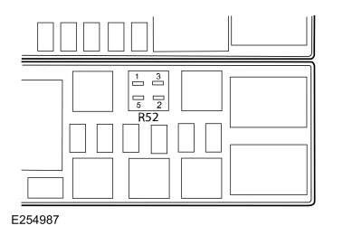 Horn relay, cavity 1


|
Refer to Wiring Diagrams Cell 44 for schematic and connector information. Normal Operation and Fault Conditions
REFER to: Horn - Overview (413-06 Horn, Description and Operation). Possible Sources
NOTICE: Use the correct probe adapter(s) when making measurements. Failure to use the correct probe adapter(s) may damage the connector. NOTICE: The following pinpoint test uses a test lamp to simulate normal circuit loads. Use only a Rotunda Test Lamp (SGT27000) or 250-300mA incandescent bulb test lamp. To avoid connector terminal damage, use the Rotunda Flex Probe kit for the test lamp probe connection to the vehicle. Do not use the test lamp probe directly on any connector. |
||||||||||||||||
| B1 CHECK THE HORN VOLTAGE SUPPLY CIRCUIT FOR AN OPEN | ||||||||||||||||
Does the test lamp illuminate?
|
||||||||||||||||
| B2 CHECK THE HORN GROUND CIRCUIT FOR AN OPEN | ||||||||||||||||
Does the test lamp illuminate?
|
|
Refer to Wiring Diagrams Cell 44 for schematic and connector information. Normal Operation and Fault Conditions
REFER to: Horn - Overview (413-06 Horn, Description and Operation). DTC Fault Trigger Conditions
Possible Sources
NOTICE: Use the correct probe adapter(s) when making measurements. Failure to use the correct probe adapter(s) may damage the connector. NOTICE: The following pinpoint test uses a test lamp to simulate normal circuit loads. Use only a Rotunda Test Lamp (SGT27000) or 250-300mA incandescent bulb test lamp. To avoid connector terminal damage, use the Rotunda Flex Probe kit for the test lamp probe connection to the vehicle. Do not use the test lamp probe directly on any connector. |
||||||||||
| C1 CHECK THE HORN RELAY OUTPUT | ||||||||||
Does the test lamp continue to illuminate?
|
||||||||||
| C2 CHECK THE HORN RELAY | ||||||||||
Did the horn relay pass the component test?
|
||||||||||
| C3 MONITOR THE BCM (BODY CONTROL MODULE) HORN_SW PID (PARAMETER IDENTIFICATION) FOR A SHORTED INPUT | ||||||||||
Does the PID status display OFF?
|
||||||||||
| C4 CHECK THE HORN RELAY CONTROL CIRCUIT FOR A SHORT TO GROUND | ||||||||||
Does the test lamp continue to illuminate?
|
||||||||||
| C5 ISOLATE THE BCM (BODY CONTROL MODULE) FOR A SHORT TO GROUND | ||||||||||
Does the test lamp continue to illuminate?
|
||||||||||
| C6 CHECK THE HORN SWITCH INPUT CIRCUIT TO THE BCM (BODY CONTROL MODULE) FOR A SHORT TO GROUND | ||||||||||
Does the test lamp illuminate?
|
||||||||||
| C7 ISOLATE THE DRIVER AIRBAG | ||||||||||
Does the test lamp illuminate?
|
||||||||||
| C8 ISOLATE THE STEERING WHEEL HARNESS | ||||||||||
Does the test lamp illuminate?
|
||||||||||
| C9 CHECK FOR CORRECT BCM (BODY CONTROL MODULE) OPERATION | ||||||||||
Is the concern still present?
|
 Description and Operation - Horn - System Operation and Component Description
System Operation
System Diagram
Item
Description
1
LH Horn
2
RH Horn
3
Horn Relay
4
BCM
5
Clockspring
6
Horn Switch
Horn Operation
The
horn switch consists of 2 sets of contacts separated by springs...
 Removal and Installation - Horn
Removal
NOTE:
Removal steps in this procedure may contain installation details.
NOTE:
LH horn shown, RH horn similar.
Remove the headlamp assembly...
Other information:
Ford Ecosport 2014-2025 Service and Repair Manual: General Procedures - Adaptive Learning Drive Cycle
Initialization NOTE: The engine and transmission must be at normal operating temperature. Using the scan tool, clear the DTC and Transmission Adaptive Tables. Bring the transmission to normal operating temperature...
Ford Ecosport 2014-2025 Service and Repair Manual: Removal and Installation - Front Door Moulding
Removal NOTE: Removal steps in this procedure may contain installation details. NOTE: LH side shown, RH side similar. NOTICE: Only use moderate force. Using a non-marring trim removal tool, disengage the retainer clips, release adhesive tape and remove moulding...
Categories
- Manuals Home
- 2nd Gen Ford Ecosport Service Manual (2014 - 2025)
- Description and Operation - Evaporative Emissions - System Operation and Component Description
- Diagnosis and Testing - Powertrain Control Module (PCM) Input and Output Controls
- Engine
- Body and Paint
- Service Information
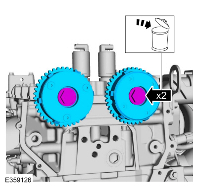
Removal and Installation - Variable Camshaft Timing (VCT) Unit
Removal
NOTICE: During engine repair procedures, cleanliness is extremely important. Any foreign material, including any material created while cleaning gasket surfaces, that enters the oil passages, coolant passages or the oil pan can cause engine failure.
Remove the timing chain.Refer to: Timing Chain (303-01C Engine - 2.0L Duratec-HE (129kW/175PS), Removal and Installation).
Remove the bolts and VCT units.
Discard the bolts.