Ford Ecosport: Instrumentation, Message Center and Warning Chimes / Description and Operation - Message Center - System Operation and Component Description
System Operation
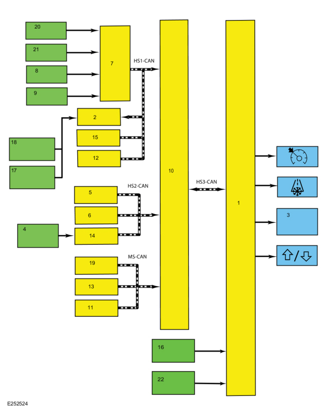
System Diagram

| Item | Description |
|---|---|
| 1 | IPC |
| 2 | PCM |
| 3 | Message center display |
| 4 | LH upper steering wheel switch |
| 5 | ABS module |
| 6 | PSCM |
| 7 | BCM |
| 8 | Liftage ajar switch |
| 9 | Brake fluid level switch |
| 10 | GWM |
| 11 | SODR |
| 12 | PAM |
| 13 | SODL |
| 14 | SCCM |
| 15 | BCM |
| 16 | Fuel level sender |
| 17 | Engine oil pressure switch (except 1.5L gas) |
| 18 | Engine oil pressure sensor (1.5L gas) |
| 19 | HVAC module |
| 20 | Door ajar switches |
| 21 | Hood ajar switch |
| 22 | Park detect switch |
Network Message Chart
Module Network Input Messages - IPC
| Broadcast Message | Originating Module | Message Purpose |
|---|---|---|
| AWD status display | PCM |
|
| Battery low state of charge | BCM | Input used to control the charging system message center warnings. |
| Brake warning indicator request | BCM | Input used to control the brake warning messages based on the parking brake and brake fluid level inputs. |
| Brake (red) warning indicator request | ABS module | Input used to control the brake warning messages. |
| Brake pedal applied message request | PCM | Input used to display the brake applied power reduced message center message. |
| Check fuel fill inlet message request | PCM | Input used to display the check fuel fill inlet message. |
| Cross traffic alert left status | SODL |
|
| Cross traffic left sensor status | SODL |
|
| Cross traffic alert right status | SODR |
|
| Cross traffic right sensor status | SODR |
|
| Cruise control status | PCM | Input used to control the cruise control RTT . |
| Cruise control set speed display | PCM | Input used to control the digital speed display. |
| Driver door ajar status | BCM |
|
| EPAS failure | PSCM | Input used to control the service power steering message display. |
| Engine coolant temperature data | PCM | Input used to display the engine over-temperature warning message. |
| Engine oil life (North America only) | PCM | Input used for the oil life display. |
| Engine overheat indication request | PCM | Input used to display the engine over-temperature warning message. |
| Engine rpm data | PCM | Input used to display the low engine oil pressure warning message. |
| Factory mode | BCM | Input used to indicate whether the vehicle is set in factory mode. |
| Fuel alcohol percent | PCM | Input used to calculate the Average Fuel Economy (AFE) and DTE based on the alcohol percent in the fuel. |
| Fuel flow volume display | PCM | Input used to calculate the Average Fuel Economy (AFE) and DTE . |
| GPS compass direction | APIM | Input used to provide the compass display. |
| Hill start assist status | ABS module | Input used to display the hill start status messages. |
| Hood ajar status | BCM | Input used to control the hood ajar warning message. |
| Ignition status | BCM |
|
| Immobilizer message display | BCM | Input used to display the passive entry and push button start messages (no key detected, place key in backup slot, restart now, key programming, accessory power active and starting system fault [PATS ]). |
| Left rear door ajar status | BCM | Input used to display the left rear door ajar warning message. |
| Liftgate ajar status | BCM | Input used to display the liftgate ajar warning message. |
| Manual gear shift indicator | PCM | Input used to control the upshift and downshift RTT indicator. |
| Oil pressure warning indicator status | PCM | Input used to display the low oil pressure message center warning. |
| Outside air temperature | HVAC module |
|
| Odometer count | PCM |
|
| Parking aid fault status | PAM | Input used to display the parking aid malfunction and service required messages. |
| Parking brake chime request | BCM | Input used to display the parking brake applied message. |
| Passenger door ajar status | BCM | Input used to display the passenger door ajar warning message. |
| Perimeter alarm chime request | BCM | Input used to display the perimeter alarm message when the vehicle is entered before deactivating the perimeter alarm. |
| Power shed level request | BCM | Input used to control the PRNDL based on the battery load shed state. |
| Powertrain cooling message request | PCM | Input used to display the reduced power to cool the engine message. |
| Right rear door ajar status | BCM | Input used to display the right rear door ajar warning message. |
| Side obstacle detect status-left | SODL |
|
| Side obstacle detect status-right | SODR |
|
| Stability-traction control chime request | ABS module | Input used to control the service AdvanceTrac® and traction control off warning displays. |
| Starting system fault message request | PCM | Input used to display starting system fault message. |
| Steering wheel message center switch data | SCCM | Input used to control the message center functions. |
| Stop/start message request | PCM | Input used to display stop-start system related informational and status messages. |
| Tire pressure data | BCM | Input used to display specific tire pressures by location. |
| Tire pressure system status | BCM |
|
| Transmission gear display | PCM | Input used to control the PRNDL not in park warning message. |
| Transport mode | BCM |
|
| Vehicle speed | PCM | Input used to control the PRNDL not in park warning message. |
Module Network Input Messages - PCM
| Broadcast Message | Originating Module | Message Purpose |
|---|---|---|
| Engine oil life data reset (North America only) | IPC | Input used to reset the oil life. |
Message Center Displays
Compass Display
The compass is displayed as a 1 or 2 character display and as a virtual compass ball (mid-level and high-level IPC only). The IPC receives the compass direction from the APIM over the HS-CAN3 .
Digital Speedometer
The IPC provides a digital speedometer display to indicate vehicle speed in a digital format. The IPC uses the internally commanded speedometer speed (based on the vehicle speed message sent from the PCM ) to provide an accurate digital speedometer display.
DTE /Average Fuel Economy (AFE)
The DTE is calculated in the IPC using the Running Average Fuel Economy (RAFE), which is the fuel economy over the last 480 km (300 miles), and the fuel level input from the fuel sender(s) to determine how many kilometers (miles) the vehicle can be driven based on the remaining fuel in the tank. The DTE can vary in the short term by up to 80 km (50 miles), but is usually within 16 km (10 miles). Even if the fuel economy is relatively constant, the DTE can be off over a 80 km (50 mile) range by -24% to +38%. The DTE display and the fuel gauge both use the fuel level input from the fuel tank to provide their respective functions. If the fuel gauge doesn't function correctly, both the fuel gauge and the DTE display are affected.
The IPC defaults to a preset baseline mpg when the battery is initially connected and changes based on driving habits and conditions.
NOTE: The actual DTE can be higher or lower than the DTE displayed in the message center due to changes in driving conditions. It is important to understand how the DTE is calculated and the factors that impact the DTE display when determining how to address any DTE concerns.
Since the DTE is calculated and averaged over a longer period of time (480 km [300 miles]), varying driving conditions can have a significant impact on the current or short term DTE as opposed to the displayed DTE . This difference often leads to customer complaints of incorrect or invalid DTE . The following list provides some (not all) of the driving conditions that may lead to an incorrect or fluctuating DTE concern:
- Changing between towing/not towing
- Changing driving between city and highway
- Allowing the vehicle to idle for long periods of time
- Using the remote start feature frequently to allow the vehicle to warm up, particularly when parked on a grade
- Parking or driving on grades
- Inconsistent use of gasoline or E85 fuels
- Over-fueling or not filling the tank completely (partial refueling)
The IPC uses the following network messages to control the DTE /Average Fuel Economy (AFE).
- Fuel alcohol percent
- Fuel flow volume display
- Odometer count
- Transport mode
The IPC receives all messages from the GWM over the HS-CAN3 . The GWM receives the transport mode message from the BCM over the HS-CAN1 and the fuel alcohol percent, fuel flow volume display and the odometer count messages from the PCM over the HS-CAN1 .
Odometer
The IPC receives the odometer count message from the GWM over the HS-CAN3 . The GWM receives the odometer count from the PCM over the HS-CAN1 . The IPC monitors the odometer count input from the GWM and commands the odometer with a digital display in the message center.
Outside Air Temperature
The Ambient Air Temperature (AAT) sensor is hardwired to the PCM through separate input and return circuits. The PCM provides a reference voltage to the Ambient Air Temperature (AAT) sensor and monitors the change in voltage resulting from changes in resistance as determined by outside air temperature.
The PCM provides the ambient air temperature data to the GWM over the HS-CAN1 . The GWM sends the ambient air temperature data message to the HVAC module over the MS-CAN . The HVAC module sends the filtered ambient air temperatue data to the IPC over the HS-CAN3 .
The HVAC module is programmed to update the messaged outside temperature data at different rates depending on several criteria (current engine temperature, engine off time and vehicle speed) to prevent false temperature displays due to a condition known as heat soaking. Heat soaking is where the outside air temperature is hotter in the location of the Ambient Air Temperature (AAT) sensor than the actual outside air temperature.
TPMS
The IPC provides a message center display showing each tire on a vehicle image to indicate specific tire pressures.
The IPC receives the tire pressure system status and tire pressure data messages from the GWM over the HS-CAN3 . The GWM receives the tire pressure system status and tire pressure data messages from the BCM over the HS-CAN1 .
RTT Indicators
Cruise Control
The IPC uses the cruise control status messaged input to control the cruise control RTT indicator.
The IPC receives the cruise control status message from the GWM over the HS-CAN3 . The GWM receives the cruise control status message from the PCM over the HS-CAN1 .
Frost
The frost RTT indicator is used to inform the driver that the outside ambient air temperature has fallen below 4° C (39° F), indicating potential icing conditions. The IPC receives the outside air temperature message from the GWM over the HS-CAN3 . The GWM receives the outside air temperature message from the HVAC module over the MS-CAN .
Upshift/Downshift (Manual Transmission Only)
The upshift/downshift indicator provides a visual cue to either upshift or downshift the vehicle to help achieve the optimum fuel economy. The IPC receives the manual gear shift indicator message from the GWM over the HS-CAN3 . The GWM receives the manual gear shift indicator message from the PCM over the HS-CAN1 .
Warning Messages
The system warning messages alert the operator to possible concerns or malfunctions in the vehicle operating systems. Warning messages are generally associated with other observable outputs of the IPC (gauges, informational indicators and RTT indicators). For example, when the BCM detects a low brake fluid condition, the BCM sends the IPC a request through the GWM to illuminate the brake warning indicator and a request to display the LOW BRAKE FLUID message in the message center. This allows the message center to be a more informative supplement to the IPC gauges and indicators.
AWD
The message center provides message center messages to inform the driver of the status of the AWD system. The IPC receives the AWD status display message from the GWM over the HS-CAN3 . The GWM receives the AWD status display message from the PCM over the HS-CAN1 .
Auto Stop-Start
The message center provides messages explaining the need for driver intervention and system status. The IPC receives the stop/start message request from the GWM over the HS-CAN3 . The GWM receives the stop/start message request from the PCM over the HS-CAN1 .
BLIS / CTA
The message center provides messages indicating the reason for the BLIS / CTA fault. The IPC receives the cross traffic alert left status, cross traffic left sensor status, cross traffic alert right status, cross traffic right sensor status, side obstacle detect status-left and side obstacle detect status-right messages from the GWM over the HS-CAN3 . The GWM receives the cross traffic alert left status, cross traffic left sensor status, cross traffic alert right status, cross traffic right sensor status, side obstacle detect status-left and side obstacle detect status-right messages from the SODL and SODR , respectively, over the MS-CAN .
Brake Applied - Power Reduced
The message center provides a brake applied warning message to inform the driver that the brake pedal and accelerator pedals are both applied. The IPC receives the brake pedal applied message request from the GWM over the HS-CAN3 . The GWM receives the brake pedal applied message request from the PCM over the HS-CAN1 .
Brake System
The IPC provides brake system messages for the following concerns and status:
- Low brake fluid level
- Parking brake applied status
- ABS concerns that display along with the brake warning indicator operation
When the parking brake is applied, the BCM sends the parking brake chime request to the GWM over the HS-CAN1 . The GWM sends the message to the IPC over the HS-CAN3 to illuminate the brake warning indicator and turn on the parking brake applied message in the message center.
When a low brake fluid level condition exists, the BCM sends the brake warning indicator request to the GWM over the HS-CAN1 . The GWM sends the message to the IPC over the HS-CAN3 to illuminate the brake warning indicator and turn on the brake fluid level low message in the message center.
When an ABS concern exists, the ABS module sends the brake (red) warning indicator request message to the GWM over the HS-CAN2 . The GWM sends the brake (red) warning indicator request message to the IPC over the HS-CAN3 to illuminate the ABS warning indictor and to turn on the check brake system message center warning display.
Charging System
The message center provides a warning message indicating the status of the charging system. When a fault is present in the charging system, the BCM sends the battery low state of charge message to the GWM over the HS-CAN1 . The IPC receives the battery low state of charge message from the GWM over the HS-CAN3 .
Check Fuel Fill Inlet
The message center provides a check fuel fill inlet message to warn the driver there is a problem with the fuel fill inlet pipe resulting in a significant evaporative emission leak following vehicle refueling. The IPC receives the check fuel fill inlet message request from the GWM over the HS-CAN3 . The GWM receives the check fuel fill inlet message request from the PCM over the HS-CAN1 .
Cold Start Fluid Level (Brazil Only)
The message center provides a cold start fluid level low warning message to inform the driver that the cold start fluid is low. The IPC receives the cold start fluid level message from the GWM over the HS-CAN3 . The GWM receives the cold start fluid level message from the PCM over the HS-CAN1 .
Door, Hood or Luggage Compartment Lid Ajar
The message center provides door, hood and liftgate ajar warnings to indicate the status of the doors, hood and liftgate. The IPC receives the driver door ajar, passenger door ajar, left rear door ajar, the right rear door ajar status, hood ajar status and liftgate ajar status messages from the GWM over the HS-CAN3 . The GWM receives the driver door ajar, passenger door ajar, left rear door ajar, the right rear door ajar status, hood ajar status and liftgate ajar status messages from the BCM over the HS-CAN1 . The BCM monitors each of the ajar inputs and sends the specific ajar status message to the IPC to display the appropriate ajar warning indicator and corresponding warning message.
EPAS
The message center provides a message to indicate there is an EPAS system concern. When a fault exists in the EPAS , the PSCM sends the EPAS failure message to the GWM over the HS-CAN2 .
The IPC receives the EPAS failure message from the GWM over the HS-CAN3 .
Engine Over-Temperature
The message center provides the engine coolant over-temperature warning message to supplement the engine over-temperature RTT and alert the driver the engine is over temperature. The IPC receives the engine overheat indication request and the engine coolant temperature data from the GWM over the HS-CAN3 . The GWM receives the engine overheat indication request and the engine over-temperature message from the PCM over the HS-CAN1 .
Factory-Transport Mode
During vehicle build, some modules, such as the IPC and the BCM , are set in factory mode. While in the factory mode the IPC displays FACTORY MODE CONTACT DEALER in the message center. If the vehicle is set in factory mode, the system does not automatically exit the mode and must be manually set to either the transport or normal operation mode.
When the vehicle build is complete, the vehicle is set to transport mode. While in transport mode, the IPC displays TRANSPORT MODE CONTACT DEALER in the message center. Transport mode is used to reduce the drain on the battery during longer periods where the vehicle is not used. Various systems may be altered or are disabled when in the transport mode. The vehicle automatically reverts to normal operation mode after being driven 201 km (125 mi).
The IPC receives the transport mode message from the GWM over the HS-CAN3 . The GWM receives the transport mode message from the BCM over the HS-CAN1 .
Gas Particular Filter (China Only)
The message center provides warning messages to inform the driver about the gas particulate filter status. The PCM provides the gas particulate filter status message to the GWM over the HS-CAN1 . The GWM provides the gas particulate filter status message to the IPC over the HS-CAN3 .
Hill Start Assist
The message center provides a message indicating the hill start assist feature is not available due to a fault in the ABS . When a fault is detected and the hill start assist is disabled, the ABS module sends the hill start assist status message to the GWM over the HS-CAN2 . The GWM sends the hill start assist status message to the IPC over the HS-CAN3 .
Load Shed
The message center provides load shed messages to inform the driver to use less options to conserve battery voltage. The IPC receives the battery low state of charge message from the GWM over the HS-CAN3 . The GWM receives the battery low state of charge message from the BCM over the HS-CAN1 .
Low Oil Pressure
The message center uses the low engine oil pressure warning message as a supplement to the low oil pressure RTT indicator to inform the driver when low engine oil pressure exists. The engine oil pressure switch is hardwired to the PCM . The PCM provides the oil pressure warning indicator status and the engine rpm data to the GWM over the HS-CAN1 . The GWM provides the oil pressure warning indicator status and engine rpm data to the IPC over the HS-CAN3 . The IPC requires engine rpm above 400 rpm before the message center displays the low oil pressure warning message.
Low Oil Level (30K Diesel Oil Life)
The message center provides a low engine oil level warning message to indicate the low oil level is low on the diesel engine with the 30k oil life. The PCM provides the engine oil level low status message to the GWM over the HS-CAN1 . The GWM provides the engine oil level low status message to the IPC over the HS-CAN3 .
Low Washer Fluid Level (Russia Only)
The low washer fluid level switch is hardwired to the IPC through a single signal circuit and is grounded through a separate ground circuit. When the IPC detects the washer fluid input pulled low, the message center displays the low washer fluid level warning message.
Oil Life
The message center provides messages to inform the driver about the oil life status and when an oil change is required. The duration of the interval between oil changes is calculated in the PCM and varies due to driving conditions. The PCM assumes a base mileage of 16,090 km (10,000 mi) or 1 year for normal driving. However, this number is adjusted down for conditions such as high engine temperature, high engine rpm, use of flex fuel and low oil level on some vehicles. The PCM calculates and provides the engine oil life percent message to the IPC . The oil change minder can be reset at any time by the driver.
The PCM receives the engine oil life data reset request from the GWM over the HS-CAN1 . The GWM receives the engine oil life data reset request from the IPC over the HS-CAN3 .
The IPC receives the engine oil life message from the GWM over the HS-CAN3 .
The GWM receives the engine oil life message from the PCM over the HS-CAN1 .
Parking Aid System
The message center provides messages to indicate the status of the parking aid system. The IPC receives the parking aid fault status message from the GWM over the HS-CAN3 . The GWM receives the parking aid fault status message from the PAM over the HS-CAN1 .
PATS And Passive Key And Immobilizer System
The message center provides the starting system fault message to indicate there is a concern with the PATS . The message center provides passive key and immobilizer system messages to indicate the key is left in the vehicle, no key is detected, accessory power is active or to press the brake to start the vehicle. The IPC uses the immobilizer message display messaged input from the BCM to display the applicable message center message.
The IPC receives the immobilizer message display request from the GWM over the HS-CAN3 .
The GWM receives the immobilizer message display request from the BCM over the HS-CAN1 .
Perimeter Alarm
The message center provides the perimeter alarm message to indicate the perimeter alarm has been activated and to start the vehicle to stop the alarm. The IPC receives the perimeter alarm chime request message from the GWM over the HS-CAN3 . The GWM receives the perimeter alarm chime request message from the BCM over the HS-CAN1 .
Powertrain Cooling
The message center provides a warning message to inform the driver that vehicle performance is reduced to allow the engine to cool. This feature is part of the smart cooling function in the PCM and provides powertrain cooling protection under high ambient temperature conditions.
The IPC receives the powertrain cooling message request from the GWM over the HS-CAN3 . The GWM receives the powertrain cooling message request from the PCM over the HS-CAN1 .
PRNDL Not In Park (Shift To Park)
The message center provides a shift to park message to inform the driver the vehicle is not in PARK (P). The IPC uses the following messages to control the shift to park message.
- Driver door ajar status
- Ignition status
- Transmission gear display
- Transport mode
- Vehicle speed
The IPC receives all required messages from the GWM over the HS-CAN3 .
The GWM receives the transmission gear display and vehicle speed messages from the PCM over the HS-CAN1 .
The GWM receives the driver door ajar status, transport mode and ignition status messages from the BCM over the HS-CAN1 .
The IPC also uses a park position detect switch (part of the selector lever) input to signal the IPC the shift lever is fully seated in the PARK (P) position. The park detect input controls the display of the "P". The IPC compares the park position detect switch input with the transmission gear display message sent from the PCM .
Stability-Traction Control
The message center provides a stability-traction control system message to indicate the stability-traction control system has a fault and requires service. When a fault condition exists in the stability-traction control system, the ABS module sets a DTC and sends the stability-traction control chime request to the GWM over the HS-CAN2 . The GWM sends the stability-traction control chime request to the IPC over the HS-CAN3 .
Starting System (Stop-Start) (If Equipped)
The message center provides starting system instructional and status messages to inform the driver of further actions required to start the engine or to explain the reason for the inability to start the engine. The IPC receives the starting system fault message request and the stop/start message request messages from the GWM over the HS-CAN3 . The GWM receives the starting system fault message request and the stop/start message request messages from the PCM over the HS-CAN1 .
TPMS
The message center provides messages to indicate the TPMS sensor training status or a malfunction in the TPMS . The IPC receives the tire pressure system status message from the GWM over the HS-CAN3 . The GWM receives the tire pressure system status message from the BCM over the HS-CAN1 .
Component Description
Low Washer Fluid Level Switch
The low washer fluid level switch is a normally closed switch that is hardwired to the IPC through a single signal wire and is grounded to a body ground through a separate circuit. The IPC provides a reference voltage to the low washer fluid level switch. When the washer fluid level is low, the float drops closing the switch and pulling the reference voltage low. When the washer fluid level is high, the float lifts off the switch and opens the circuit to the IPC sending the reference voltage high.
Steering Wheel Switch - Message Center
The message center switch is the upper LH steering wheel switch and is comprised of 5 buttons. The message center switch uses different resistance values associated with each specific button. The IPC sends out a reference voltage to the upper LH steering wheel switch on the input circuit and monitors the voltage drop. The voltage drop varies depending upon the resistance of the specific button pressed, providing indication to the IPC which switch is pressed.
 Description and Operation - Message Center - Overview
Overview
The message center is an integral part of the IPC that receives and
acts upon much of the same information that is input and used to operate
the IPC
(gauges, informational indicators, and warning indicators)...
 Description and Operation - Warning Chimes - Overview
Overview
The warning chimes provide the driver with audible warnings that act
as reminders and supplemental alerts to visual IPC indications such as
gauges, indicators and message center warnings...
Other information:
Ford Ecosport 2014-2026 Service and Repair Manual: Description and Operation - Glass, Frames and Mechanisms - Overview
Overview Delayed Accessory Feature The power windows operate only when the delayed accessory feature is active. The delayed accessory feature is active whenever the ignition is ON, or up to 10 minutes after the ignition is changed from ON to OFF while the driver and passenger doors remain closed...
Ford Ecosport 2014-2026 Service and Repair Manual: Removal and Installation - Rear Fender Splash Shield
Removal NOTE: Removal steps in this procedure may contain installation details. NOTE: LH side shown, RH side similar. Disengage the pushpin and the clips, position aside the rocker panel moulding. Remove the pushpin and the retainers...
Categories
- Manuals Home
- 2nd Gen Ford Ecosport Service Manual (2014 - 2026)
- Removal and Installation - Starter Motor
- Removal and Installation - Catalytic Converter
- Body and Paint
- Removal and Installation - Fuel Pump and Sender Unit
- Description and Operation - Evaporative Emissions - System Operation and Component Description
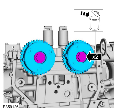
Removal and Installation - Variable Camshaft Timing (VCT) Unit
Removal
NOTICE: During engine repair procedures, cleanliness is extremely important. Any foreign material, including any material created while cleaning gasket surfaces, that enters the oil passages, coolant passages or the oil pan can cause engine failure.
Remove the timing chain.Refer to: Timing Chain (303-01C Engine - 2.0L Duratec-HE (129kW/175PS), Removal and Installation).
Remove the bolts and VCT units.
Discard the bolts.