Ford Ecosport: Cruise Control / Description and Operation - Cruise Control - System Operation and Component Description
System Operation
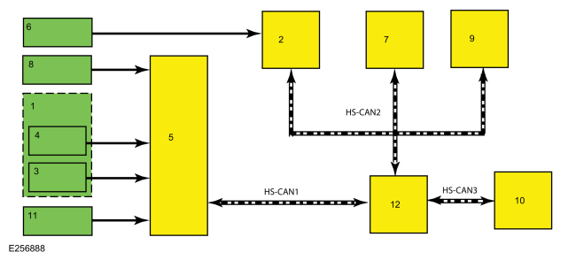
System Diagram

| Item | Description |
|---|---|
| 1 | Brake Pedal |
| 2 | SCCM |
| 3 | Deactivator Switch |
| 4 | Stoplamp Switch |
| 5 | PCM |
| 6 | Cruise Control/ ASL Switches |
| 7 | RCM |
| 8 | Accelerator Pedal |
| 9 | ABS |
| 10 | IPC |
| 11 | Clutch Pedal Switch |
| 12 | GWM |
Network Message Chart
Network Input Messages - Instrument Panel Cluster (IPC)
| Broadcast Message | Originating Module | Message Purpose |
|---|---|---|
| Cruise control status | PCM | Data used for speed control indicator status. |
| Adjustable speed limiter (ASL) chime request | PCM | Audible indicator used for the Adjustable Speed Limiter (ASL) feature when the set speed has been exceeded. |
| Adjustable speed limiter (ASL) status | PCM | Data used for adjustable speed limiter (ASL) indicator status. |
Network Input Messages - Powertrain Control Module (PCM)
| Broadcast Message | Originating Module | Message Purpose |
|---|---|---|
| Cruise control button status | SCCM | Used for cruise control enable/disable and operating mode request. |
| Adjustable Speed Limiter (ASL) switch position | BCM | Activates Adjustable Speed Limiter (ASL) feature when requested. |
| Stability control event in progress | ABS module | Deactivates speed control when requested. |
| Traction control event in progress |
Cruise Control Operation
The cruise control functions include:
- turning on the cruise control system.
- setting and maintaining the desired vehicle speed.
- accelerating the vehicle speed.
- coasting down to a lower speed.
- resuming the prior vehicle speed.
- turning off the cruise control system.
Hardwired inputs to the PCM are:
- Digital TR sensor
- BPP switch assembly (contains the stoplamp switch and cruise control deactivator switch)
- Clutch pedal cruise control deactivator switch (if equipped)
- APP sensor
Hardwired outputs of the PCM are:
- Electronic Throttle Body (ETB) command
The vehicle speed is controlled by the PCM through the Electronic Throttle Control (ETC) subsystem.
The cruise control system provides self-diagnostics. Cruise control is disabled anytime an error is detected in the system. No IPC indicator or message center messages are displayed when faults occur. Fault codes are logged by the PCM or SCCM .
An Electronic Throttle Control (ETC) system fault also causes the cruise control system to be disabled. In this case, an Electronic Throttle Control (ETC) system powertrain malfunction (wrench) warning indicator is displayed.
Additionally, certain conditions cause the cruise control system to deactivate:
- Transmission gear selector is placed into a position other than D or OD
- Cruise control set speed is overridden with the accelerator pedal for a period longer than 5 minutes
- Cruise control switch is pressed or stuck longer than 2 minutes
- Clutch pedal depressed (if equipped)
- ABS fault
Cruise Control Indicator
The cruise control indicator, located in the IPC , illuminates to indicate the cruise control system is active.
Steering Wheel Switch Function
Cruise control switch inputs are received by the SCCM and sent to the GWM on the HS-CAN . The GWM then sends the switch information to the PCM .
Pressing and releasing the ON/OFF switch turns the cruise control system on. Pressing up (SET+) or down (SET-) on the SET switch while the vehicle is traveling at the desired speed activates the cruise control system.
While the cruise control system is active, applying the brake pedal or pressing the CAN/RES switch puts the cruise control system into standby mode. Pressing the CAN/RES switch when the cruise control system is in standby mode causes the vehicle to accelerate to the last set speed. Resume does not function if the ON/OFF switch is pressed, the ignition is cycled OFF or if the current vehicle speed is below the minimum operational speed.
Pressing the SET switch up or down while in the active mode increases or decreases the maintained vehicle speed by 1.6 kmh (1 mph) per press. If the respective switch is pressed and held, the vehicle speed continues to accelerate or decelerate until the switch is released.
Pressing and releasing the ON/OFF switch while the cruise control is active or the ignition is cycled OFF, turns the cruise control system off.
Adjustable Speed Limiter (ASL) Operation
The Adjustable Speed Limiter (ASL) feature is mutually exclusive of the cruise control system. The feature allows the driver to set a desired speed that the vehicle cannot exceed during normal driving conditions. Unlike cruise control, the vehicle slows down when the accelerator pedal is released.
Pressing the Adjustable Speed Limiter (ASL) switch (LIM) on the steering wheel turns the Adjustable Speed Limiter (ASL) feature on and off. Pressing the cruise control switch (SET+) and (SET-) buttons selects the desired speed limit. Any speed can be selected within the minimum to maximum range of 30 kph (18 mph) to 180 kph (112 mph). The speed selection is indicated in the instrument cluster.
Adjustable Speed Limiter (ASL) inputs are received by the SCCM and sent to the GWM on the HS-CAN . The GWM sends the switch information to the PCM on the HS-CAN indicating the system is activated.
The front wheel speed sensors monitor the vehicle speed. When the vehicle reaches the selected set speed, the PCM limits the amount of fuel delivered to the engine, preventing the vehicle from traveling beyond the set speed.
The Adjustable Speed Limiter (ASL) speed limit can be overridden, without pressing the steering wheel switch or by pressing the accelerator pedal to 90% of travel. The speed limit automatically resumes when the accelerator pedal is released and the vehicle slows down to below the set speed limit. If the system is not overridden and the set speed limit is exceeded, an audible chime sounds and a message displays in the instrument cluster.
The Adjustable Speed Limiter (ASL) operates exclusive of the cruise control and is not connected to the brakes or the clutch (if equipped). Applying the brake pedal or clutch pedal does not override or deactivate the Adjustable Speed Limiter (ASL).
Component Description
Steering Wheel Switches
The cruise control steering wheel mounted switches are momentary contact switches. Each steering wheel switch function corresponds to a specific resistance value. The SCCM sends out a 5-volt reference voltage to the steering wheel switch and monitors the voltage when a switch is pressed. The voltage varies depending upon the resistance of the specific switch pressed, indicating which switch is pressed.
Brake Switch
When the brake pedal is applied, an electrical signal from the stoplamp circuit to the PCM deactivates the cruise control system. Under increased brake pedal effort, the cruise control deactivator switch opens and removes the ground signal from the PCM input circuit releasing the throttle, immediately deactivating the cruise control system.
Clutch Switch
Vehicles equipped with a manual transmission have an additional clutch pedal cruise control deactivator switch. The clutch pedal cruise control deactivator switch is a normally open switch with the clutch pedal released. When the clutch pedal is pressed, an electrical signal is sent from the clutch pedal speed control deactivator switch circuit to the PCM which deactivates the cruise control system.
 Description and Operation - Cruise Control - Overview
Overview
The cruise control system and Adjustable Speed Limiter (ASL) are controlled by the PCM .
The
cruise control mode is selected from the steering wheel mounted
switches (ON/OFF, SET+, SET- and CAN/RES), which are integrated into the
LH steering wheel switch...
 Diagnosis and Testing - Cruise Control
DTC Chart: PCM
Diagnostics in this manual assume a certain skill level and knowledge of Ford-specific diagnostic practices. REFER to: Diagnostic Methods (100-00 General Information, Description and Operation)...
Other information:
Ford Ecosport 2014-2025 Service and Repair Manual: Removal and Installation - Turbine Shaft Speed (TSS) Sensor
Removal With the vehicle in NEUTRAL, position it on a hoist. Refer to: Jacking and Lifting - Overview (100-02 Jacking and Lifting, Description and Operation). Disconnect the TSS sensor electrical connector...
Ford Ecosport 2014-2025 Service and Repair Manual: Removal and Installation - Rear Lower Arm
Special Tool(s) / General Equipment Transmission Jack Removal NOTICE: Suspension fasteners are critical parts that affect the performance of vital components and systems. Failure of these fasteners may result in major service expense...
Categories
- Manuals Home
- 2nd Gen Ford Ecosport Service Manual (2014 - 2025)
- Removal and Installation - Catalytic Converter
- Removal and Installation - Fuel Pump and Sender Unit
- Diagnosis and Testing - Evaporative Emissions
- Removal and Installation - Rear Bumper
- Automatic Transmission - 6-Speed Automatic Transmission – 6F35
Removal and Installation - Rear Halfshaft Seal
Special Tool(s) / General Equipment
 205-153
(T80T-4000-W)
205-153
(T80T-4000-W)
Handle
 205-990
Installer, Axle Seal
TKIT-2012A-FL
TKIT-2012A-ROW