Ford Ecosport: Engine - 2.0L Duratec-HE (129kW/175PS) / Assembly - Engine
Special Tool(s) /
General Equipment
 |
100-002
(TOOL-4201-C)
Holding Fixture with Dial Indicator Gauge |
 |
205-153
(T80T-4000-W)
Handle |
 |
303-096
(T74P-6150-A)
Installer, Camshaft Front Oil Seal
TKIT-2009TC-F |
 |
303-103
(T74P-6375-A)
Holding Tool, Flywheel
T74P-77000-A
TKIT-2009TC-F |
 |
303-1247
VCT Spark Plug Tube Seal Remover and Installer
TKIT-2006UF-FLM
TKIT-2006UF-ROW |
 |
303-1521
Alignment Tool, Crankshaft Position Sensor
TKIT-2010C-FLM |
 |
303-1565
Alignment Tool, Camshaft
TKIT-2010C-FLM |
 |
303-328
(T88P-6701-B1)
Replacer, Rear Seal
TKIT-1988-FLM
TKIT-1988-F
TKIT-1988-LM |
 |
303-507
Timing Peg, Crankshaft TDC
TKIT-2001N-FLM
TKIT-2001N-ROW |
| Feeler Gauge |
| Floor Crane |
| Hose Clamp Remover/Installer |
| Round-Ended Steel Rule |
| Piston Ring Compressor |
Materials
| Name |
Specification |
Motorcraft® Metal Surface Prep Wipes
ZC-31-B |
-
|
Motorcraft® Silicone Gasket and Sealant
TA-30 |
WSE-M4G323-A4
|
Motorcraft® Gasket Maker
TA-16 |
WSK-M2G348-A5
|
NOTICE:
Do not loosen or remove the crankshaft pulley bolt without first
installing the special tools as instructed in this procedure. The
crankshaft pulley and the crankshaft timing sprocket are not keyed to
the crankshaft. The crankshaft, the crankshaft sprocket and the pulley
are fitted together by friction. For that reason, the crankshaft
sprocket is also unfastened if the pulley bolt is loosened. Before any
repair requiring loosening or removal of the crankshaft pulley bolt, the
crankshaft and camshafts must be locked in place by the special service
tools, otherwise severe engine damage can occur.
NOTICE:
During engine repair procedures, cleanliness is extremely
important. Any foreign material, including any material created while
cleaning gasket surfaces that enters the oil passages, coolant passages
or the oil pan, can cause engine failure.
NOTE:
If it is necessary to install a new timing chain tensioner, a
cast iron tensioner is to be replaced with an aluminum tensioner
(6K254). The existing bolts must be discarded and replaced with new
bolts (6K282).
NOTE:
Assembly of the engine requires various inspections/measurements
of the engine components (engine block, crankshaft, connecting rods,
pistons and piston rings). These inspections/measurements will aid in
determining if the engine components will require replacement.
NOTE:
Refer to exploded views in Description and Operation.
-
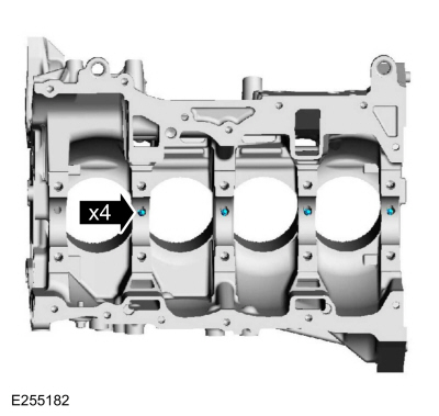
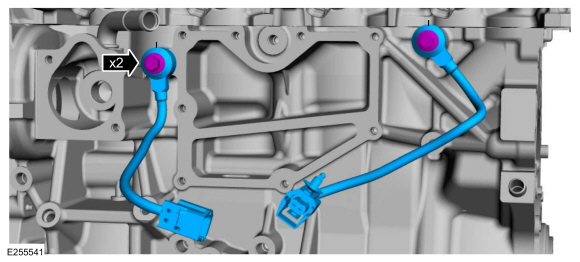
NOTE:
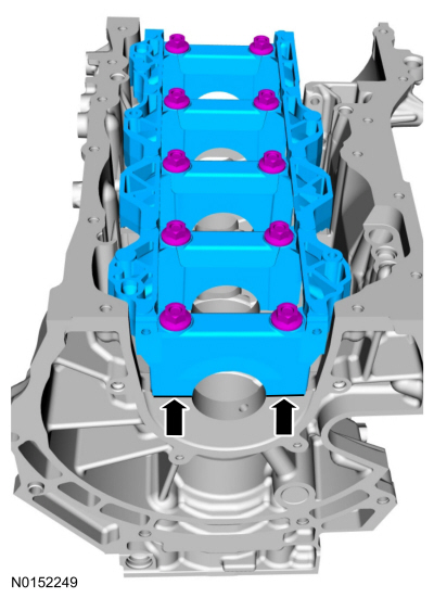
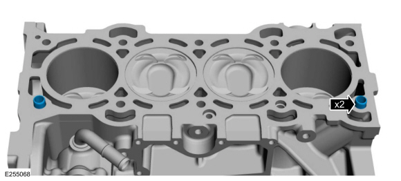
If the engine piston oil coolers are being reused, they
must be installed in the same location as marked during disassembly.
NOTE:
The front bulkhead does not have an engine piston oil cooler.
Install the engine piston oil coolers and the bolts.
Torque:
35 lb.in (4 Nm)
-
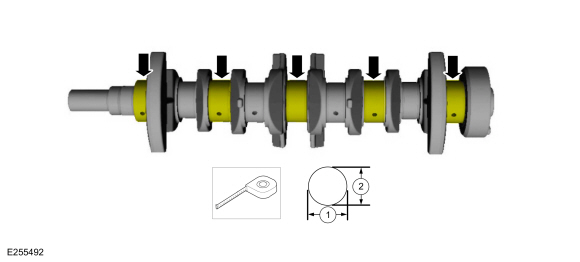
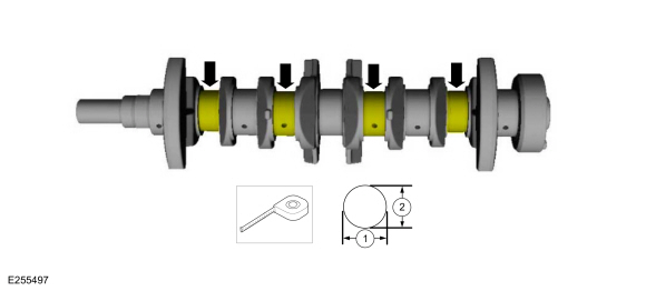
Measure each of the crankshaft main bearing journal
diameters in at least 2 directions and record the smallest diameter for
each journal.
-
Position the main bearing beam in the engine block with the
main bearing beam mounted flush with the rear face of the engine block
and install the original main bearing beam bolts finger tight.
-
Tighten the bolts in sequence shown.
Torque:
Stage 1:
44 lb.in (5 Nm)
Stage 2:
18 lb.ft (25 Nm)
Stage 3:
90°
-
Measure each crankshaft block main bearing bore diameter.
-
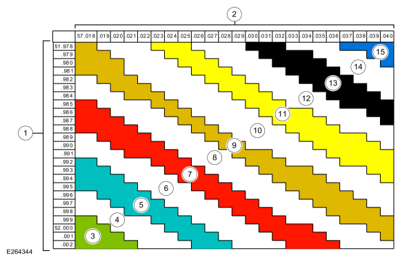
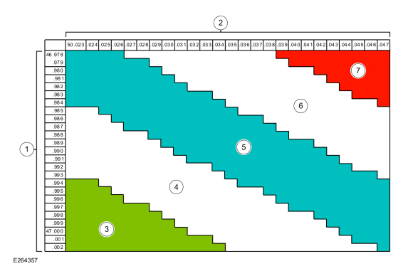
NOTE:
The bearing color corresponds to the number marked on the bearing.
Using the chart, select the correct grade main bearings.
-
Crankshaft journal diameter
-
Cylinder block bore diameter
-
Upper Bearing Green: 1 / Lower Bearing Green: 1
-
Upper Bearing Blue: 2 / Lower Bearing Green: 1
-
Upper Bearing Blue: 2 / Lower Bearing Blue: 2
-
Upper Bearing Red: 3 / Lower Bearing Blue: 2
-
Upper Bearing Red: 3 / Lower Bearing Red: 3
-
Upper Bearing Brown: 4 / Lower Bearing Red: 3
-
Upper Bearing Brown: 4 / Lower Bearing Brown: 4
-
Upper Bearing Yellow: 5 / Lower Bearing Brown: 4
-
Upper Bearing Yellow: 5 / Lower Bearing Yellow: 5
-
Upper Bearing Black: 6 / Lower Bearing Yellow: 5
-
Upper Bearing Black: 6 / Lower Bearing Black: 6
-
Upper Bearing Blue/Green: 7 / Lower Bearing Black: 6
-
Upper Bearing Blue/Green: 7 / Lower Bearing Blue/Green: 7
-
Using the original connecting rod cap bolts, install the
connecting caps and bolts and tighten the bolts in 2 stages:
Torque:
Stage 1:
21 lb.ft (29 Nm)
Stage 2:
90°
-
-
Measure the connecting rod large end bore in 2 directions.
-
Record the smallest measurement for each connecting rod.
-
-
Remove the bolts and the connecting rod caps.
-
-
Measure each of the crankshaft connecting rod bearing journal diameters in at least 2 directions.
-
Record the smallest measurement for each connecting rod journal.
-
NOTE:
The bearing color corresponds to the number marked on the bearing.
Using the chart, select the correct grade connecting rod bearings.
-
Crankshaft journal diameter
-
Connecting rod diameter
-
Upper Bearing Green: 1 / Lower Bearing Green: 1
-
Upper Bearing Green: 1/ Lower Bearing Blue: 2
-
Upper Bearing Blue: 2 / Lower Bearing Blue: 2
-
Upper Bearing Blue: 2/ Lower Bearing Red: 3
-
Upper Bearing Red: 3 / Lower Bearing Red: 3
-
-
Remove the bolts in the sequence shown and the main bearing beam.
-
Discard the main bearing beam bolts.
-
NOTE:
Before assembling the cylinder block, all sealing
surfaces must be free of chips, dirt, paint and foreign material. Make
sure the coolant and oil passages are clear.
NOTE:
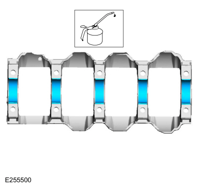
If reusing the crankshaft main bearings, install them in
their original positions and orientation as noted during disassembly.
NOTE:
The center bulkhead is the thrust bearing.
Lubricate with clean engine oil and install the crankshaft main bearings.
-
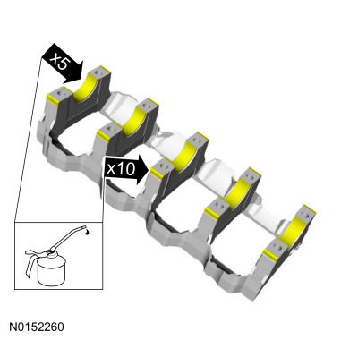
NOTE:
If reusing the crankshaft main bearings, install them in
their original positions and orientation as noted during disassembly.
Lubricate with clean engine oil and install the main bearing beam bearings.
-
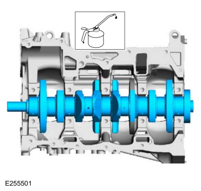
Lubricate with clean engine oil and install the crankshaft.
-
Lubricate the main bearing beam side fit surfaces and the 5 main bearing beam bearings with clean engine oil.
-
Position the main bearing beam in the engine block with the
main bearing beam mounted flush with the rear face of the engine block.
-
NOTE:
Position the crankshaft to the rear of the cylinder
block, then position the crankshaft to the front of the cylinder block
before tightening the main bearing beam bolts.
-
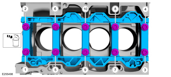
Lubricate the main bearing beam bolt threads and under the bolt heads with clean engine oil.
-
Install the 10 new main bearing beam bolts finger tight.
-
Position the crankshaft to the rear of the cylinder
block, then position the crankshaft to the front of the cylinder block
before tightening the main bearing beam bolts.
-
Tighten the main bearing beam bolts in sequence shown in 3 stages.
Torque:
Stage 1:
44 lb.in (5 Nm)
Stage 2:
18 lb.ft (25 Nm)
Stage 3:
90°
 |
|
-
-
Measure crankshaft end play.
Use Special Service Tool: 100-002
(TOOL-4201-C)
Holding Fixture with Dial Indicator Gauge.
-
Position the crankshaft to the rear of the cylinder block.
-
Zero the Dial Indicator Gauge with Holding Fixture.
-
Move the crankshaft to the front of the cylinder block.
-
Note and record the crankshaft end play.
-
Acceptable crankshaft end play is 0.2-0.43 mm
(0.008-0.017 in). If the crankshaft end play exceeds the specified
range, install new parts as necessary.
-
-
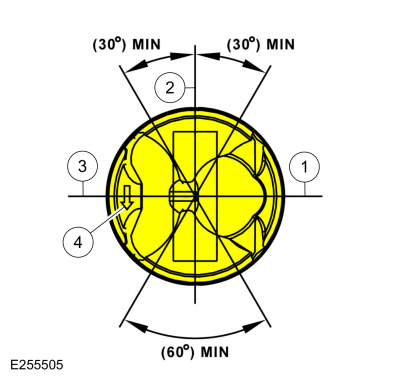
Upper oil control segment ring gap location.
-
Oil control spacer gap location.
-
Lower oil control segment ring gap location.
-
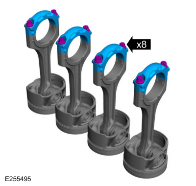
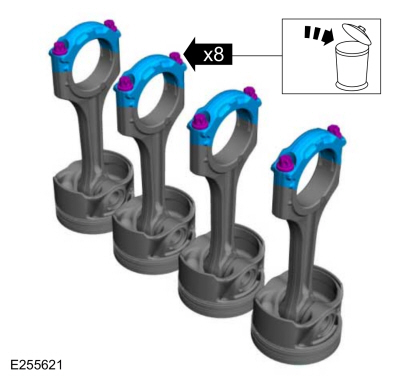
Piston to be assembled with the arrow pointing to the front of the engine.
-
Connecting rod to be assembled with the front marks pointing to the front of the engine.
-
NOTICE:
Be sure not to scratch the cylinder wall or crankshaft
journal with the connecting rod. Push the piston down until the
connecting rod bearing seats on the crankshaft journal.
NOTE:
Lubricate the pistons, piston rings, connecting rod bearings and the entire cylinder bores with clean engine oil
NOTE:
Make sure the piston arrow on top is facing toward the front of the engine.
NOTE:
When installing the pistons and connecting rod
assemblies, the oil ring gaps must be positioned 60 degrees apart from
each other and a minimum of 90 degrees from the expander gap. The
position of the upper and lower compression ring gaps are not controlled
for installation.
Install the piston and connecting rod assemblies.
Use the General Equipment: Piston Ring Compressor
-
Install the original crankshaft pulley bolt.
-
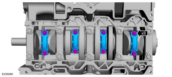
NOTICE:
The rod cap installation must keep the same orientation as marked during disassembly or engine damage may occur.
NOTE:
Install connecting rod caps and bolts on the connecting
rods for cylinders 1 and 4 first and tighten. Then rotate crankshaft 180
degrees and install connecting rod caps and bolts on connecting rods
for cylinders 2 and 3 and tighten.
NOTE:
After installation of each connecting rod cap, rotate the crankshaft to verify smooth operation.
Install the connecting rod caps and the new bolts and tighten the bolts in 2 stages:
Torque:
Stage 1:
21 lb.ft (29 Nm)
Stage 2:
90°
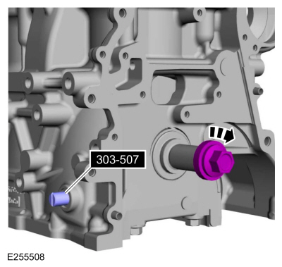
-
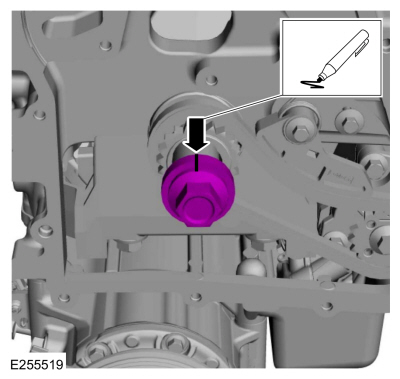
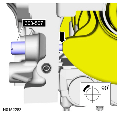
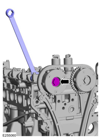
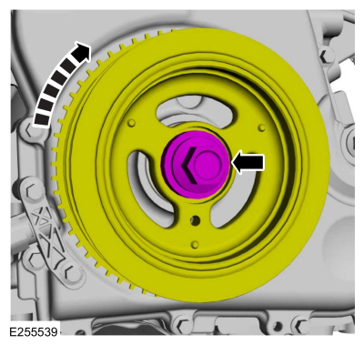
Install the special tool and rotate the crankshaft pulley
bolt slowly clockwise until the crankshaft balance weight is up against
the special tool. The engine is now at TDC .
Use Special Service Tool: 303-507
Timing Peg, Crankshaft TDC.
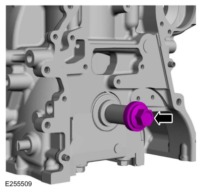
-
Remove the crankshaft pulley bolt.
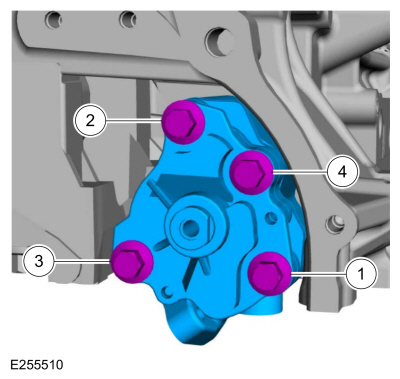
-
Install the oil pump assembly and tighten the bolts in the sequence shown in 2 stages.
Material: Motorcraft® Metal Surface Prep Wipes
/ ZC-31-B
Torque:
Stage 1:
89 lb.in (10 Nm)
Stage 2:
177 lb.in (20 Nm)
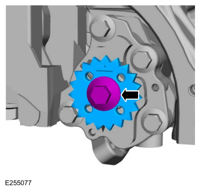
-
Install the oil pump sprocket and bolt.
Torque:
18 lb.ft (25 Nm)
-
Install the crankshaft sprocket.
-
-
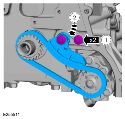
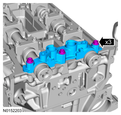
Install the chain on the oil pump sprocket and install the tensioner and the shoulder bolts.
Torque:
89 lb.in (10 Nm)
-
Push the tensioner spring down and position the spring under the shoulder bolt.
-
-
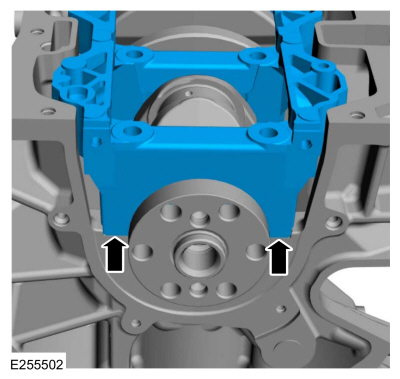
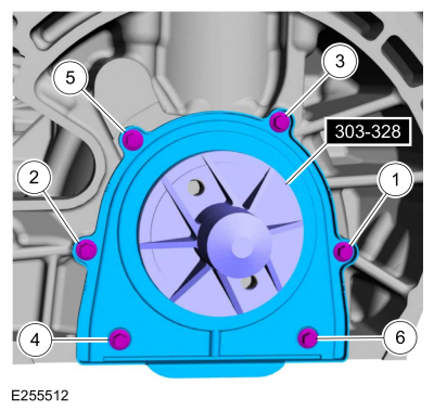
Install the crankshaft rear main oil seal installer.
Use Special Service Tool: 303-328
(T88P-6701-B1)
Replacer, Rear Seal.
-
Using the crankshaft rear main oil seal installer,
position the crankshaft rear oil seal with retainer plate onto the
crankshaft.
Torque:
89 lb.in (10 Nm)
-
Install a new oil pickup and screen O-ring seal.
-
Using a new gasket, install the oil pump screen and pickup tube and the bolts.
Torque:
89 lb.in (10 Nm)
-
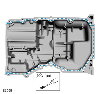
NOTE:
If the oil pan is not secured within 10 minutes of
sealant application, the sealant must be removed and the sealing area
cleaned with metal surface prep. Allow to dry until there is no sign of
wetness, or 10 minutes, whichever is longer. Failure to follow this
procedure can cause future oil leakage.
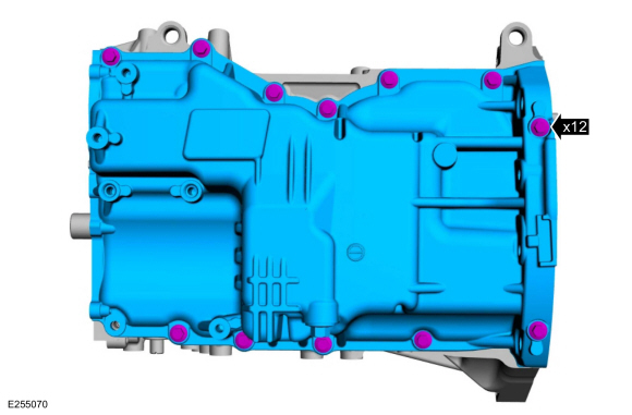
Apply a bead of Silicone Gasket and Sealant to the oil pan-to-engine block mating surface.
Material: Motorcraft® Silicone Gasket and Sealant
/ TA-30
(WSE-M4G323-A4)
-
Position the oil pan onto the engine and install the bolts finger-tight.
-
Align the front surface of the oil pan flush with the front surface of the engine block.
Use the General Equipment: Round-Ended Steel Rule
-
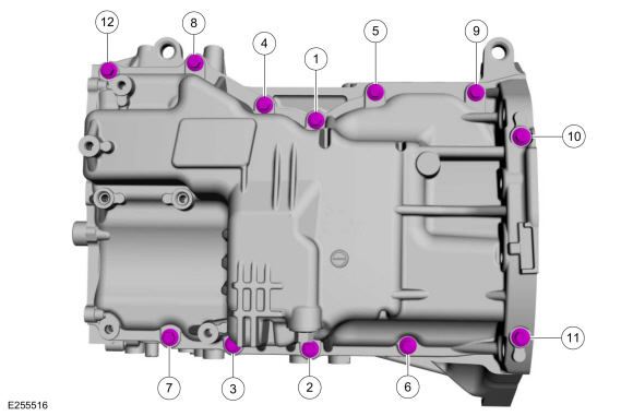
Tighten in sequence shown.
Torque:
177 lb.in (20 Nm)
-
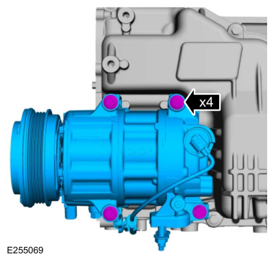
Install the A/C compressor and the bolts.
Torque:
18 lb.ft (25 Nm)
-
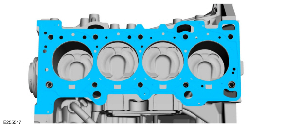
Install the cylinder head alignment dowels.
-
Install a new cylinder head gasket.
-
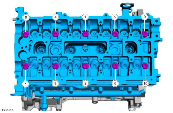
NOTE:
The cylinder head bolts are torque-to-yield and must not be reused. New cylinder head bolts must be installed.
Install the cylinder head and the new bolts. Tighten the bolts in sequence shown in 5 stages.
Torque:
Stage 1:
62 lb.in (7 Nm)
Stage 2:
133 lb.in (15 Nm)
Stage 3:
26 lb.ft (35 Nm)
Stage 4:
90°
Stage 5:
135°
-
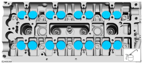
NOTE:
Lubricate the valve tappets with clean engine oil prior to installing.
Install the valve tappets in their original positions.
-
NOTICE:
If any new parts are being installed (cylinder head,
valves, tappets, camshafts) it is necessary to check the valve
clearance, follow the next 13 steps exactly or serious damage to the
engine may occur. If the original parts are being installed it is not
necessary to check the valve clearance so proceed to step 55.
Install the crankshaft bolt and place a paint mark on the crankshaft bolt at the 12 o'clock position.
-
-
Remove Special Service Tool: 303-507
Timing Peg, Crankshaft TDC.
-
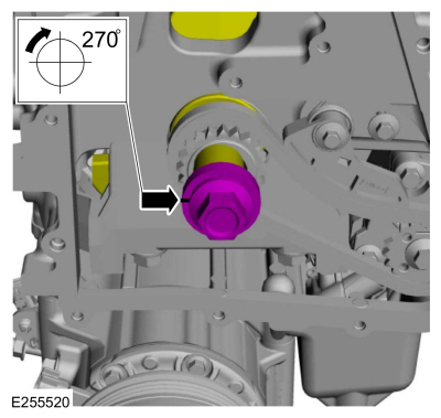
NOTE:
Rotating the crankshaft will position all of the pistons
below the deck of the cylinder block and allow the camshafts to be
installed and the valve clearance checked without the possibility of
damage to the valves or pistons.
Using the crankshaft bolt and washer, rotate the crankshaft
clockwise 270 degrees until the paint mark is at the 9 o'clock position.
-
NOTICE:
Failure to follow the camshaft tightening procedure can result in damage to the camshafts.
-
Lubricate the camshaft journals, camshafts and camshaft
bearing caps with clean engine oil and install the camshafts, caps and
bolts.
-
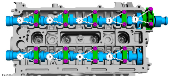
Tighten 2 turns at a time in the sequence shown in 2 stages.
Torque:
Stage 1:
62 lb.in (7 Nm)
Stage 2:
142 lb.in (16 Nm)
-
Lubricate the camshaft journals with clean engine oil and install the front camshaft bearing cap and bolts.
Torque:
Stage 1:
62 lb.in (7 Nm)
Stage 2:
142 lb.in (16 Nm)
-
-
Using the flats of the camshaft, rotate the camshaft to
place the cam lobe at base circle, with the lobe pointed away from the
tappet.
-
Use a feeler gauge to measure the clearance of each valve and record its location.
Use the General Equipment: Feeler Gauge
-
Repeat to measure all of the lobe/tappet clearances.
-
NOTE:
The number on the valve tappet only reflects the digits
that follow the decimal. For example, a tappet with the number 0.650 has
the thickness of 3.650 mm.
NOTE:
Select tappets using this formula: tappet thickness =
measured clearance + the existing tappet thickness - nominal clearance.
NOTE:
The nominal clearance is:
-
intake: 0.25 mm (0.0095 in).
-
exhaust: 0.36 mm (0.0142 in).
NOTE:
The acceptable clearances after being fully installed are:
-
intake: 0.19-0.31 mm (0.007-0.012 in).
-
exhaust: 0.30-0.42 mm (0.012-0.017 in).
Select the closest tappet size to the ideal tappet thickness available and mark the installation location.
-
Remove the bolts and the front camshaft bearing cap.
-
NOTICE:
Failure to follow the camshaft loosening procedure can result in damage to the camshafts.
Loosen the camshaft bearing caps in sequence 2 turns at a
time until all tension is released from the camshaft bearing caps.
Remove the bolts, caps and camshafts.
-
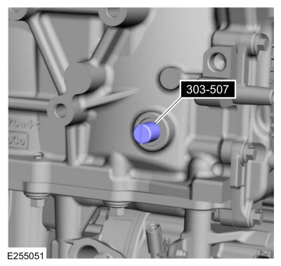
Install Special Service Tool: 303-507
Timing Peg, Crankshaft TDC.
-
NOTE:
Rotating the crankshaft will position the engine at TDC and allow you
to install the camshafts in the same position as noted during the
disassembly.
Using the crankshaft pulley bolt, rotate the crankshaft
clockwise 90 degrees so the crankshaft contacts the special tool.
-
Remove and discard crankshaft pulley bolt.
-
NOTE:
Lubricate the valve tappets with clean engine oil prior to installing.
If necessary, replace any tappets with the correct tappets
selected during the valve clearance check and lubricate with clean
engine oil.
-
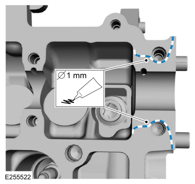
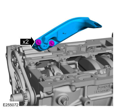
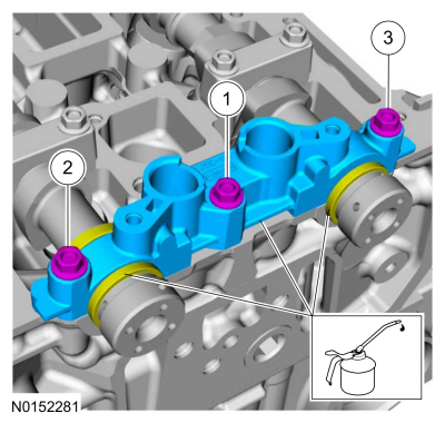
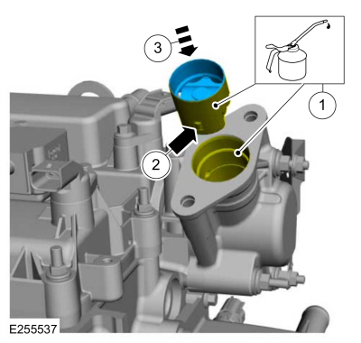
NOTE:
The exhaust camshaft rear bearing cap must be secured
within 10 minutes of Gasket Maker application. If the exhaust camshaft
rear bearing cap is not secured within 10 minutes, the sealant must be
removed and the sealing area cleaned with Motorcraft Metal Surface Prep.
NOTE:
Do not allow Gasket Maker to enter the camshaft bearing
journal. If Gasket Maker is applied to the camshaft bearing journal,
the journal and sealing area must be cleaned with Motorcraft Metal
Surface Prep.
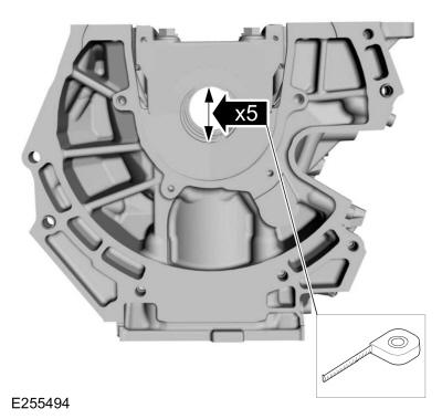
Apply 1 mm (0.039 in) beads of Gasket Maker to the exhaust rear camshaft bearing cap as shown.
Material: Motorcraft® Gasket Maker
/ TA-16
(WSK-M2G348-A5)
 |
|
-
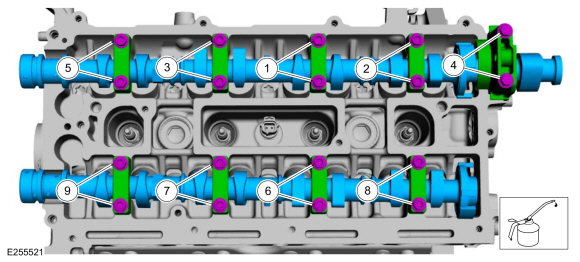
NOTICE:
Install the camshafts with the alignment slots in the
camshafts lined up so the Camshaft Alignment Plate can be installed
without rotating the camshafts. Make sure the lobes on the No. 1
cylinder are in the same position as noted in the removal procedure.
Rotating the camshafts when the timing chain is removed, or installing
the camshafts 180 degrees out of position can cause severe damage to the
valves and pistons.
NOTICE:
Failure to follow the camshaft tightening procedure can result in damage to the camshafts.
NOTICE:
Wipe off any excess gasket maker from the fuel injection
pump housing sealing surface of the cylinder head and rear camshaft
cap.
-
Lubricate the camshaft journals, camshafts and camshaft
bearing caps with clean engine oil and install the camshafts, caps and
bolts.
-
Tighten the camshaft bearing cap bolts one turn at a time, until finger-tight.
-
Tighten 2 turns at a time in the sequence shown in 2 stages.
Torque:
Stage 1:
62 lb.in (7 Nm)
Stage 2:
142 lb.in (16 Nm)
 |
|
-
-
Lubricate the camshaft journals with clean engine oil.
-
Install the front camshaft bearing cap and the bolts and tighten in 2 stages.
Torque:
Stage 1:
62 lb.in (7 Nm)
Stage 2:
142 lb.in (16 Nm)
-
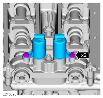
Install the VCT solenoids and the bolts.
Torque:
89 lb.in (10 Nm)
-
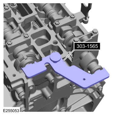
NOTICE:
The special tool is for camshaft alignment only. Using
this tool to prevent engine rotation can result in engine damage.
Install Special Service Tool: 303-1565
Alignment Tool, Camshaft.
-
NOTE:
The VCT unit bolts are final torqued in the timing drive installation.
Install the intake and exhaust camshaft phaser and sprockets and the new bolts finger-tight.
-
Install the tensioner arm, timing chain, timing chain guide and the bolts.
Torque:
89 lb.in (10 Nm)
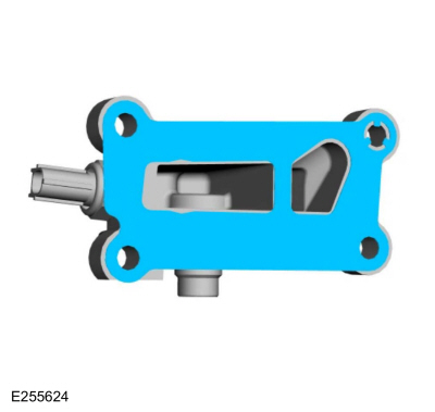
NOTE:
If equipped with aluminum timing chain tensioner.
NOTE:
If the timing chain tensioner plunger is not pinned in the compressed position, follow the next step.
-
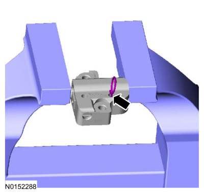
Reset the timing chain tensioner.
-
Position the timing chain tensioner in a soft-jawed vise.
-
Spread the ends of the ratchet wire clip apart.
-
Using the soft-jawed vise, compress the plunger to the reset position.
-
Install a locking pin in the 2 holes of the timing chain tensioner body to hold the plunger in place.
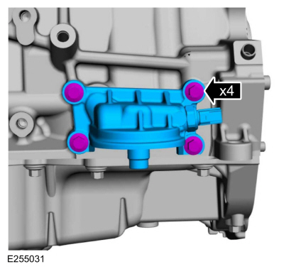
-
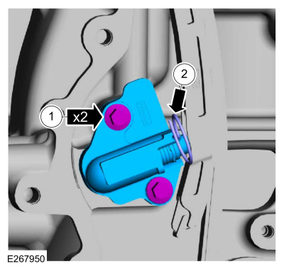
NOTE:
If equipped with aluminum timing chain tensioner.
NOTE:
Do not remove the locking pin until the tensioner bolts are tightened.
-
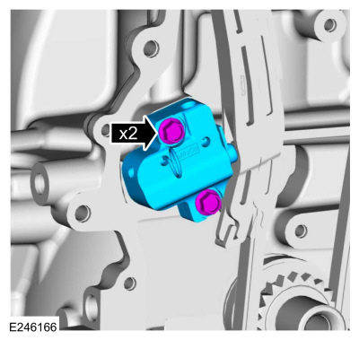
Install the timing chain tensioner and the bolts.
Torque:
89 lb.in (10 Nm)
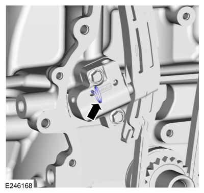
-
Remove the locking pin.
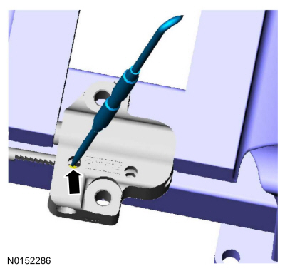
NOTE:
If equipped with cast iron timing chain tensioner.
NOTE:
If the timing chain tensioner plunger and ratchet assembly are
not pinned in the compressed position, follow the next 4 steps.
-
NOTICE:
Do not compress the ratchet assembly. This will damage the ratchet assembly.
Using the edge of a vise, compress the timing chain tensioner plunger.
-
Using a small pick, push back and hold the ratchet mechanism.
-
While holding the ratchet mechanism, push the ratchet arm back into the tensioner housing.
-
Install a locking pin into the hole in the tensioner housing
to hold the ratchet assembly and the plunger in during installation.
-
NOTE:
If equipped with cast iron timing chain tensioner.
NOTE:
Do not remove the locking pin until the tensioner bolts are tightened.
Install the timing chain tensioner and the bolts.
Torque:
89 lb.in (10 Nm)
-
NOTE:
If equipped with cast iron timing chain tensioner.
Remove the locking pin.
-
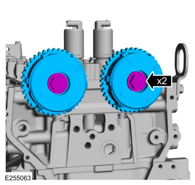
NOTICE:
The Camshaft Alignment Tool is for camshaft alignment
only. Using this tool to prevent engine rotation can result in engine
damage.
NOTE:
Using the flats on the camshafts to prevent camshaft rotation.
Tighten the sprocket bolts shown in 2 stages:
Torque:
Stage 1:
44 lb.ft (60 Nm)
Stage 2:
90°
-
NOTE:
The engine front cover must be secured within 10 minutes
of Silicone Gasket and Sealant application. If the engine front cover
is not secured within 10 minutes, the sealant must be removed and the
sealing area cleaned.
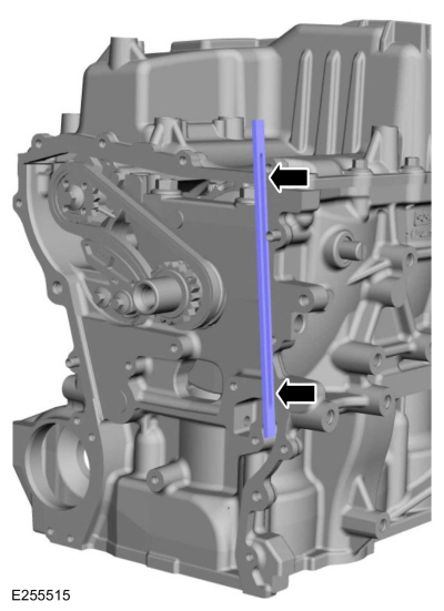
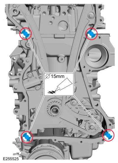
Apply a 15 mm (0.59 in) drop of silicone sealant at the
cylinder head-to-cylinder block and cylinder block-to-oil pan joint
areas.
Material: Motorcraft® Silicone Gasket and Sealant
/ TA-30
(WSE-M4G323-A4)
-
NOTE:
The engine front cover must be secured within 10
minutes of Silicone Gasket and Sealant application. If the engine front
cover is not secured within 10 minutes, the sealant must be removed and
the sealing area cleaned with Motorcraft Metal Surface Prep.
Apply silicone sealant as shown.
Material: Motorcraft® Silicone Gasket and Sealant
/ TA-30
(WSE-M4G323-A4)
-
Install the engine front cover and the bolts finger tight.
-
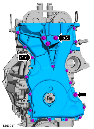
Tighten the engine front cover bolts in sequence shown.
-
Tighten bolts 1 through 3 to
Torque:
35 lb.ft (48 Nm)
-
Tighten bolts 4 through 13 to
Torque:
89 lb.in (10 Nm)
-
Tighten bolt 14 to
Torque:
35 lb.ft (48 Nm)
-
Tighten bolts 15 through 21 to
Torque:
89 lb.in (10 Nm)
-
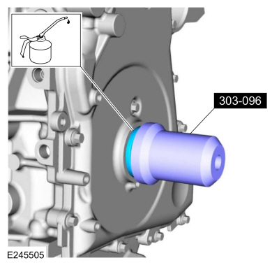
NOTE:
Remove the through-bolt from the special tool .
Lubricate with clean engine oil and using the special tool, install the crankshaft front seal.
Use Special Service Tool: 303-096
(T74P-6150-A)
Installer, Camshaft Front Oil Seal.
-
Lubricate the crankshaft pulley with clean engine oil.
-
NOTE:
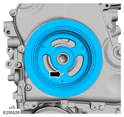
Do not install the crankshaft pulley bolt at this time.
NOTE:
Apply clean engine oil on the seal area before installing.
Position the crankshaft pulley onto the crankshaft with the crankshaft pulley TDC guide hole at the 6 o'clock position.
-
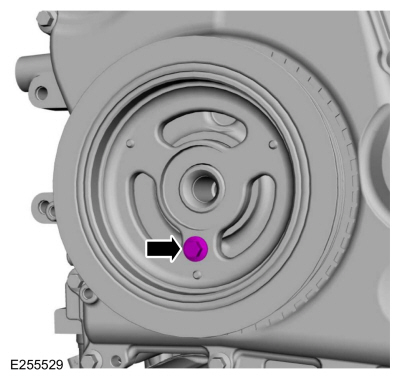
NOTE:
This step will correctly align the crankshaft pulley to the crankshaft.
Install a standard M6 bolt through the crankshaft pulley TDC guide hole and into the engine front cover.
-
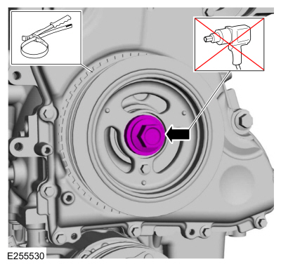
NOTICE:
The crankshaft must remain in the TDC
position during installation of the pulley bolt or damage to the
engine can occur. Therefore, the crankshaft pulley must be held in place
with the special tool and a new bolt should be installed using hand
tools only.
NOTE:
Do not reuse the crankshaft pulley bolt. Install a new crankshaft pulley bolt
-
Install a new crankshaft pulley bolt finger tight.
-
Using a strap wrench to hold crankshaft pulley, tighten the crankshaft pulley bolt in 2 stages.
Torque:
Stage 1:
74 lb.ft (100 Nm)
Stage 2:
90°
-
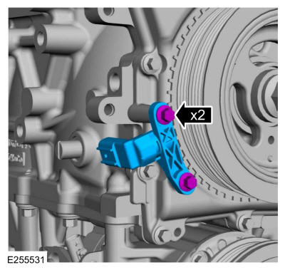
Remove the M6 bolt.
-
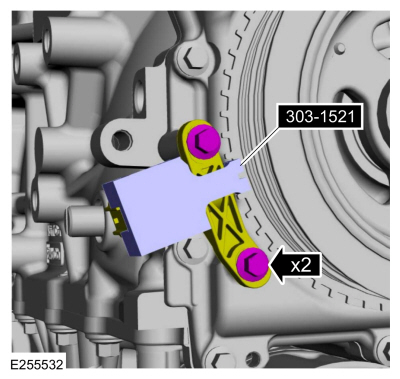
Install the CKP sensor and the bolts finger-tight.
-
Install the special tool to set the CKP sensor position and tighten the 2 bolts.
Use Special Service Tool: 303-1521
Alignment Tool, Crankshaft Position Sensor.
Torque:
62 lb.in (7 Nm)
-
Remove Special Service Tool: 303-1521
Alignment Tool, Crankshaft Position Sensor.
-
Remove Special Service Tool: 303-507
Timing Peg, Crankshaft TDC.
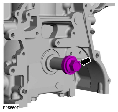
-
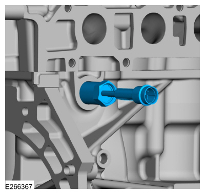
Install the engine plug bolt.
Torque:
177 lb.in (20 Nm)
-
Remove Special Service Tool: 303-1565
Alignment Tool, Camshaft.
-
NOTE:
Installation of new seals is only required if damaged seals were removed during disassembly of the engine.
Using the special tools, install the VCT oil control solenoid seals.
Use Special Service Tool: 303-1247
VCT Spark Plug Tube Seal Remover and Installer.
, 205-153
(T80T-4000-W)
Handle.
-
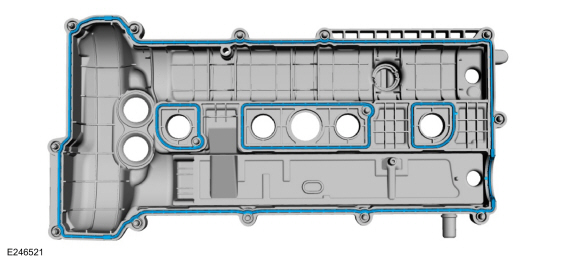
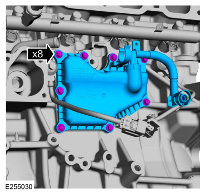
NOTE:
The valve cover must be secured within 10 minutes of
silicone gasket application. If the valve cover is not secured within 10
minutes, the sealant must be removed and the sealing area cleaned with
Motorcraft Metal Surface Prep.
Apply a 6 mm bead of silicone sealant.
Material: Motorcraft® Silicone Gasket and Sealant
/ TA-30
(WSE-M4G323-A4)
-
Install new valve cover gaskets.
-
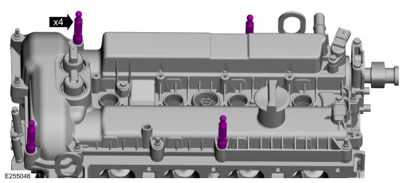
Install the valve cover and tighten the fasteners in sequence shown.
Torque:
89 lb.in (10 Nm)
-
Install the engine appearance cover holders.
Torque:
27 lb.in (3 Nm)
-
-
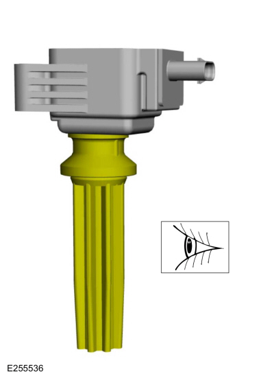
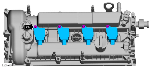
Inspect the ignition coil boot for rips, nicks or tears.
-
Remove and discard the damaged ignition coil boots.
-
Install the ignition coil-on-plugs and the fasteners.
Torque:
89 lb.in (10 Nm)
-
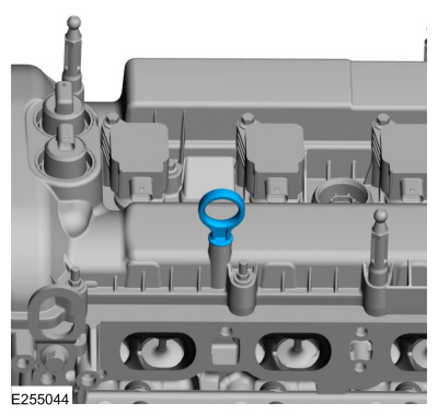
Install the oil level indicator.
-
Install the coolant outlet and the bolts.
Torque:
89 lb.in (10 Nm)
-
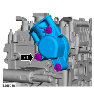
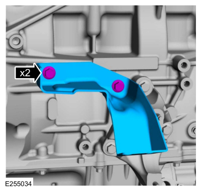
Install the high-pressure fuel pump drive unit and the stud bolts and tighten in 2 stages.
Torque:
Stage 1:
71 lb.in (8 Nm)
Stage 2:
60°
-
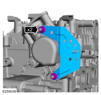
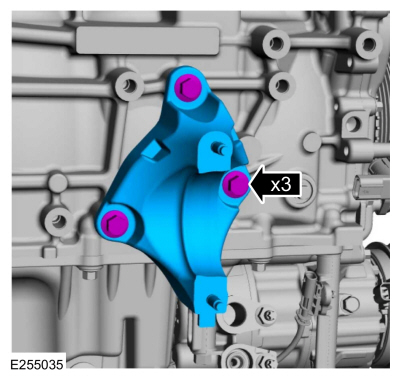
Install the high-pressure fuel pump bracket and the bolts.
Torque:
133 lb.in (15 Nm)
-
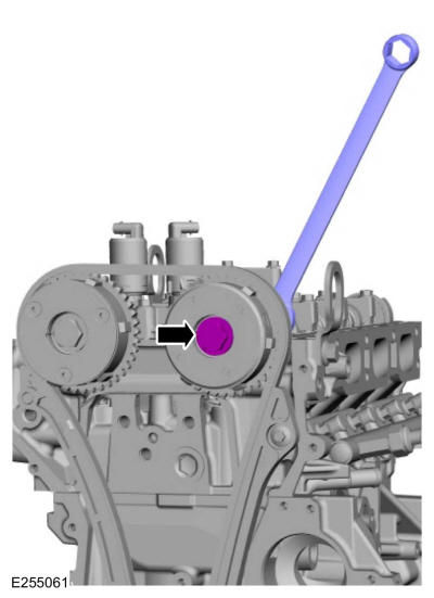
NOTICE:
Only rotate the crankshaft clockwise or damage to the engine may occur.
Turn the crankshaft clockwise until the fuel injection pump cam lobe is at BDC .
-
NOTE:
The cam lobe for the fuel injection pump must be at BDC for the fuel injection pump installation.
-
Lubricate the high-pressure fuel pump tappet and high-pressure fuel pump drive unit bore with clean engine oil.
-
Align the high-pressure fuel pump tappet with the high-pressure fuel pump drive unit.
-
Install the high-pressure fuel pump tappet.
-
Install a new high-pressure fuel pump O-ring seal and lubricate with clean engine oil.
-
Install the fuel injection pump and loosely install new fuel
injection pump bolts, alternately tighten each bolt one complete
revolution until seated.
Torque:
Stage 1:
177 lb.in (20 Nm)
Stage 2:
45°
-
Install the bracket and the bolts.
Torque:
35 lb.ft (48 Nm)
-
Install the bracket and the bolts.
Torque:
18 lb.ft (25 Nm)
-
NOTICE:
The RH KS must be installed in the 6 o'clock position and the LH KS
must be installed in the 4 o'clock position. Failure to follow these
instructions may result in damage to the engine.
Install the KS and the bolts.
Torque:
177 lb.in (20 Nm)
-
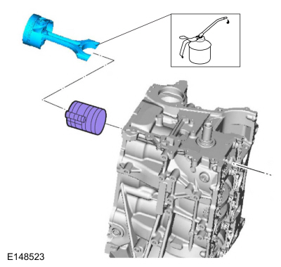
Install a new oil filter adapter gasket.
-
Install the oil filter adapter and the bolts.
Torque:
18 lb.ft (25 Nm)
-
Install the crankcase vent separator and the bolts.
Torque:
89 lb.in (10 Nm)
-
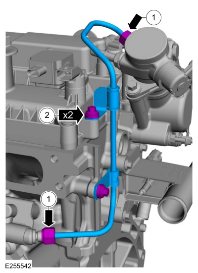
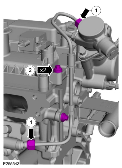
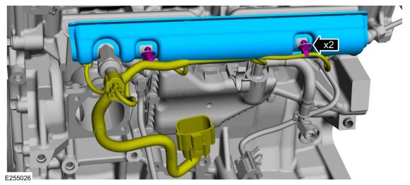
-
Install the fuel tube and the nuts finger-tight.
-
Install the bolts finger-tight.
-
NOTE:
Calculate the correct torque wrench setting for the following torque. REFER to Torque Wrench Adapter Formulas.
-
Tighten the high pressure fuel tube flare nuts in the following 2 stages:
Torque:
Stage 1:
133 lb.in (15 Nm)
Stage 2:
45°
-
Tighten the bolts.
Torque:
89 lb.in (10 Nm)
-
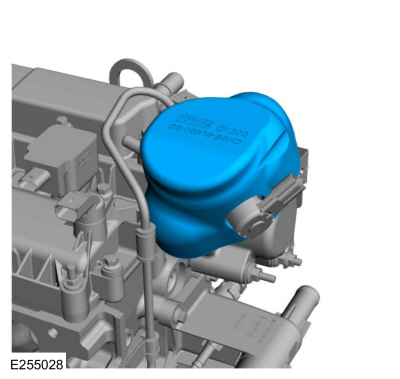
NOTE:
Use care when installing the fuel injection pump noise
insulator. Spreading the openings will aid in installing the fuel
injection pump noise insulator and reduce the risk of damage.
Install the high-pressure fuel pump noise insulator.
-
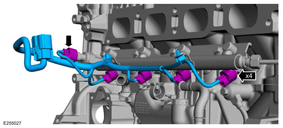
-
Connect the fuel injector electrical connectors.
-
Connect the FRP sensor electrical connector.
-
Install the fuel rail insulator and attach the fuel rail wiring harness retainers.
-
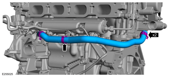
-
Install the coolant hose.
Use the General Equipment: Hose Clamp Remover/Installer
-
Attach the coolant hose retainer.
-
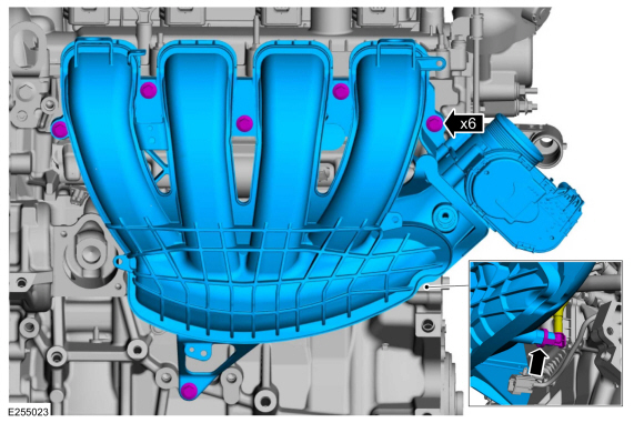
NOTICE:
If the engine is repaired or replaced because of upper
engine failure, typically including valve or piston damage, check the
intake manifold for metal debris. If metal debris is found, install a
new intake manifold. Failure to follow these instructions can result in
engine damage.
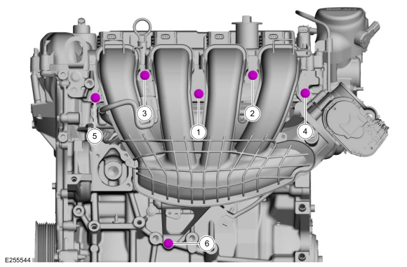
-
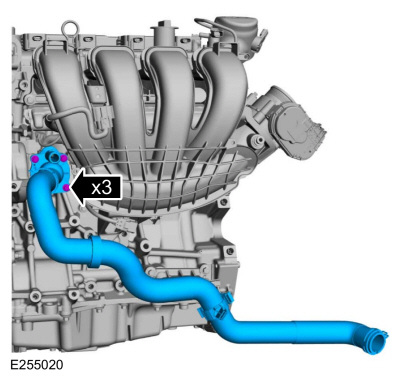
Install the intake manifold and the bolts finger-tight.
-
Tighten the bolts in sequence shown.
Torque:
177 lb.in (20 Nm)
-
Attach the KS wiring harness connectors to the intake manifold.
-
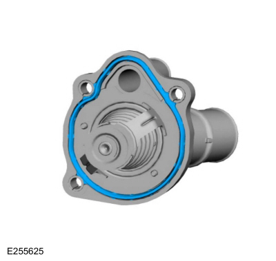
Install a new thermostat housing gasket.
-
Install the thermostat housing and the bolts.
Torque:
89 lb.in (10 Nm)
-
Install the coolant hoses and the clamp.
Use the General Equipment: Hose Clamp Remover/Installer
-
Position the coolant hoses and install the clamp.
Use the General Equipment: Hose Clamp Remover/Installer
-
If equipped, install the block heater.
Torque:
41 lb.ft (55 Nm)
-
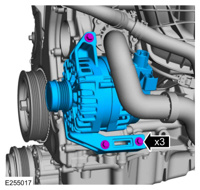
Install the generator and the bolts.
Torque:
18 lb.ft (25 Nm)
-
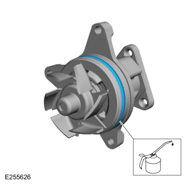
Install a new coolant pump O-ring seal and lubricate with clean engine coolant.
-
Install the coolant pump and the bolts.
Torque:
89 lb.in (10 Nm)
-
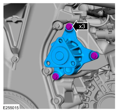
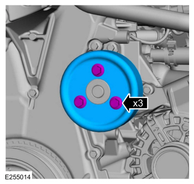
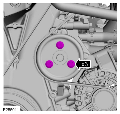
Install the coolant pump pulley and the bolts finger-tight.
-
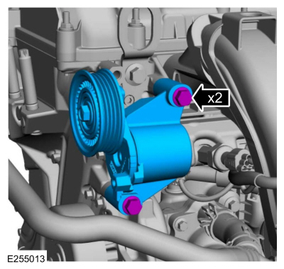
Install the accessory drive belt tensioner and the bolts.
Torque:
18 lb.ft (25 Nm)
-
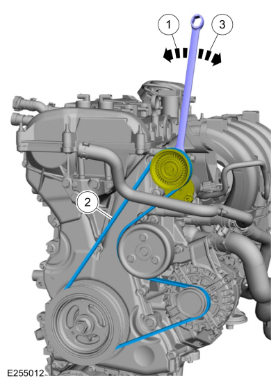
-
Install the tool and release the tension on the accessory drive belt tensioner.
-
Install the accessory drive belt.
-
Release the tool and remove.
-
Tighten the coolant pump pulley bolts.
Torque:
177 lb.in (20 Nm)
-
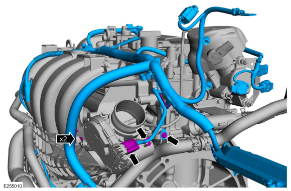
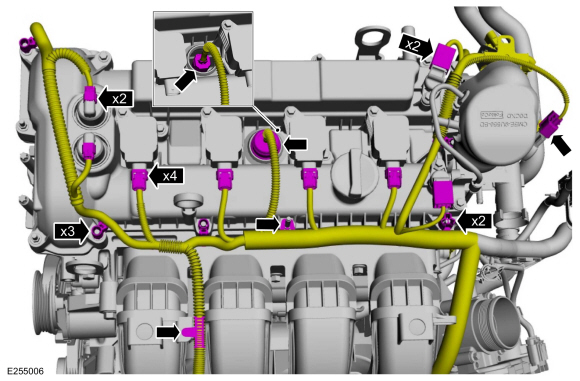
-
Install the engine wiring harness and attach the wiring harness retainers.
-
Connect throttle body wiring harness electrical connector and retainer.
-
Install the ground cable and the bolt.
Torque:
89 lb.in (10 Nm)
-
-
Attach the generator wiring harness retainer to the coolant hose.
-
Connect the generator electrical connector.
-
Install battery B+ cable and the nut.
Torque:
150 lb.in (17 Nm)
-
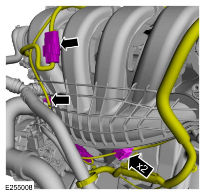
-
Connect KS wiring harness electrical connectors.
-
Attach the wiring harness retainer to the intake manifold.
-
Connect and attach the fuel rail wiring harness electrical connector.
-
Connect the ECT sensor electrical connector and attach the wiring harness retainers.
-
-
Attach the wiring harness retainers.
-
Connect the CMP sensor electrical connectors.
-
Connect the CHT sensor electrical connector and install cover.
-
Connect the ignition coil-on-plug electrical connectors.
-
Connect the VCT oil control solenoid electrical connectors.
-
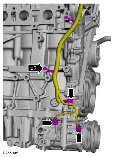
-
Connect the CKP and A/C compressor electrical connectors.
-
Attach the wiring harness retainers.
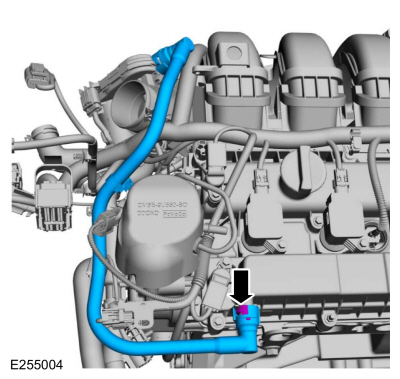
-
Connect the crankcase vent tube from the valve cover.
Refer to: Quick Release Coupling (310-00 Fuel System -
General Information - 2.0L Duratec-HE (129kW/175PS), 2.0L Duratec-HE
(125kW/170PS) – MI4, 2.0L Duratec-HE Flex Fuel (129kW/175PS))
.
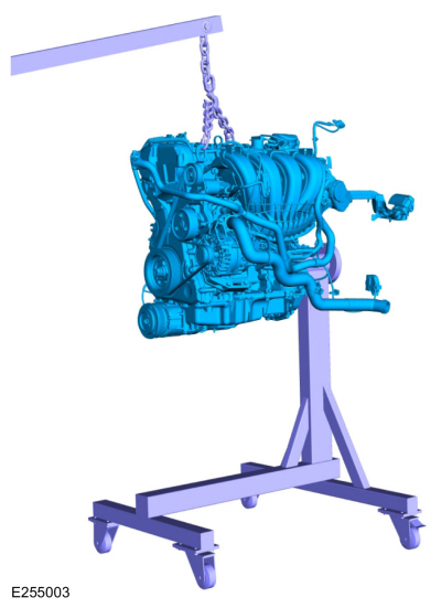
-
Install the lift equipment and floor crane.
Use the General Equipment: Floor Crane
-
Remove the engine from the engine stand.
-
NOTE:
Special bolts are used for installation. Do not use standard bolts.
-
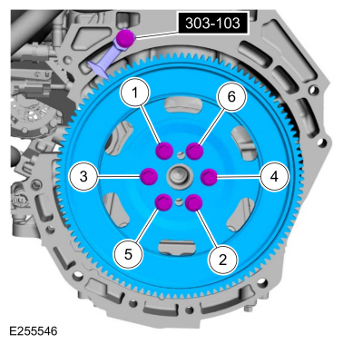
Install the flexplate and the bolts finger tight.
-
Install Special Service Tool: 303-103
(T74P-6375-A)
Holding Tool, Flywheel.
-
Tighten the bolts in sequence shown in 3 stages.
Torque:
Stage 1:
37 lb.ft (50 Nm)
Stage 2:
59 lb.ft (80 Nm)
Stage 3:
83 lb.ft (112 Nm)
DISASSEMBLY
Remove the piston rings and discard.
Remove the piston pin retainers and discard...
Special Tool(s) /
General Equipment
307-566Retainer, Torque ConverterTKIT-2006C-FFMFLMTKIT-2006C-LMTKIT-2006C-ROW
Magnetic Socket
Floor Crane
Adjustable Mounting Arm
Hose Clamp Remover/Installer
Powertrain Jack
Wooden Block
Materials
Name
Specification
Motorcraft® Multi-Purpose Grease SprayXL-5-A
ESB-M1C93-B ..
Other information:
B00C5:11, B00C5:12, B00C5:13, B00C5:1D
Refer to Wiring Diagrams Cell 46 for schematic and connector information.
Normal Operation and Fault Conditions
The RCM continuously monitors the passenger seat position sensor circuits for the following faults:
Open circuit
Short to voltage
Short to ground
Current out of range
Faulted passenger s..
Disassembled Views
Auto-Start-Stop
Item
Part Number
Description
1
70057005
Transmission case
2
7A1307A130
Clutch support tower
3
7D0197D019
Clutch support tower seals (4 required)
4
W302855W302855
Clutch support tower bolt (3 required)
5
7F2427F242
No..


 Disassembly and Assembly of Subassemblies - Piston
 Installation - Engine