Ford Ecosport: Engine - 2.0L Duratec-HE (129kW/175PS) / Installation - Engine
Special Tool(s) /
General Equipment
 |
307-566
Retainer, Torque Converter
TKIT-2006C-FFMFLM
TKIT-2006C-LM
TKIT-2006C-ROW |
| Magnetic Socket |
| Floor Crane |
| Adjustable Mounting Arm |
| Hose Clamp Remover/Installer |
| Powertrain Jack |
| Wooden Block |
Materials
| Name |
Specification |
Motorcraft® Multi-Purpose Grease Spray
XL-5-A |
ESB-M1C93-B
|
Motorcraft® Threadlock and Sealer
TA-25-B |
-
|
Motorcraft® R-1234yf Refrigerant PAG Oil
YN-35 |
WSS-M2C300-A2
|
Motorcraft® Silicone Brake Caliper Grease and Dielectric Compound
XG-3-A |
ESA-M1C200-A
ESE-M1C171-A
|
Motorcraft® MERCON® LV Automatic Transmission Fluid
XT-10-QLVC |
WSS-M2C938-A
MERCON® LV,
|
All vehicles
-
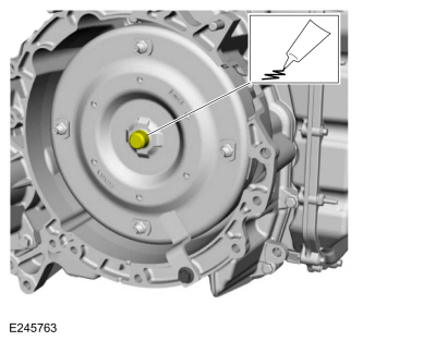
Lubricate the torque converter pilot hub with multi-purpose grease.
Material: Motorcraft® Multi-Purpose Grease Spray
/ XL-5-A
(ESB-M1C93-B)
-
Remove Special Service Tool: 307-566
Retainer, Torque Converter.
-
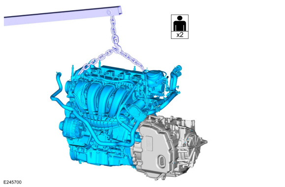
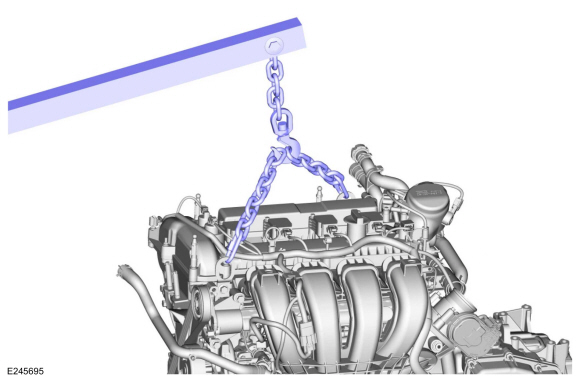
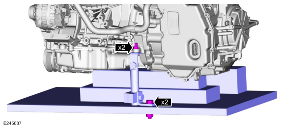
Using the floor crane and engine lift equipment, install the engine to the transmission on the powertrain table.
Use the General Equipment: Floor Crane
-
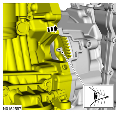
Make sure the torque converter stud marked during removal aligns with the flexplate.
-
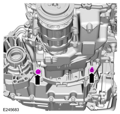
Install the transmission-to-engine bolt.
Torque:
35 lb.ft (48 Nm)
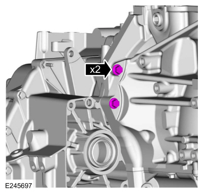
-
Install the transmission-to-engine bolts.
Torque:
35 lb.ft (48 Nm)
-
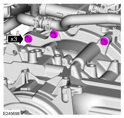
Install the engine-to-transmission bolts.
Torque:
35 lb.ft (48 Nm)
-
Install adjustable mounting arm.
Use the General Equipment: Adjustable Mounting Arm
-
Remove the floor crane and engine lift equipment.
Use the General Equipment: Floor Crane
-
Tighten the engine mount studs.
Torque:
93 lb.in (10.5 Nm)
-
NOTICE:
Rotate the engine in a clockwise direction only or engine damage may occur.
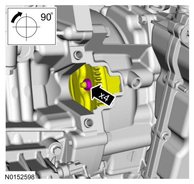
Install new torque converter nuts.
Use the General Equipment: Magnetic Socket
Torque:
30 lb.ft (40 Nm)
-
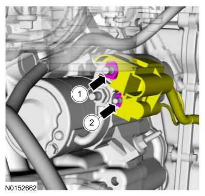
Install the starter motor isolator.
-
Install the starter motors and the stud bolts.
Torque:
26 lb.ft (35 Nm)
-
-
Position the starter motor wiring housing and install the battery positive cable nut.
Torque:
106 lb.in (12 Nm)
-
Install the motor control wire nut.
Torque:
53 lb.in (6 Nm)
-
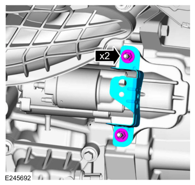
Install the starter motor bracket and the nuts.
Torque:
89 lb.in (10 Nm)
-
-
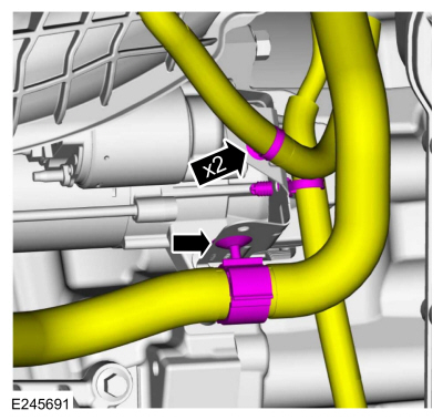
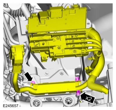
Attach the wiring harness retainers.
-
Attach the coolant hose retainer.
-
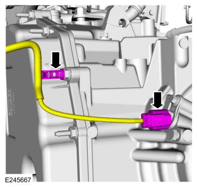
Connect the transmission wiring harness electrical connector and retainer.
-
-
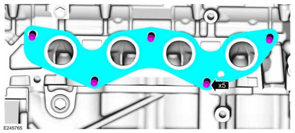
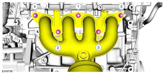
Install the catalytic converter manifold stud bolts.
Torque:
150 lb.in (17 Nm)
-
Install the catalytic converter manifold gasket.
-
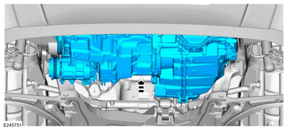
Raise the powertrain into the vehicle.
-
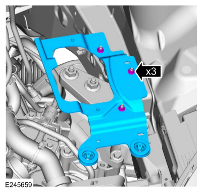
Install the transmission mount bolt.
Torque:
46 lb.ft (63 Nm)
-
-
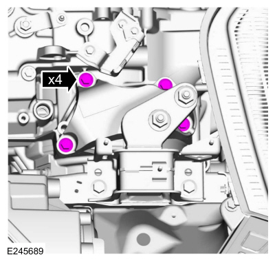
Install the engine mount and the nuts.
Torque:
59 lb.ft (80 Nm)
-
Install the engine mount bolts.
Torque:
66 lb.ft (90 Nm)
-
-
Remove adjustable mounting arm.
Use the General Equipment: Adjustable Mounting Arm
-
Remove the powertrain jack and boards from under the engine and transmission.
Use the General Equipment: Powertrain Jack
Use the General Equipment: Wooden Block
-
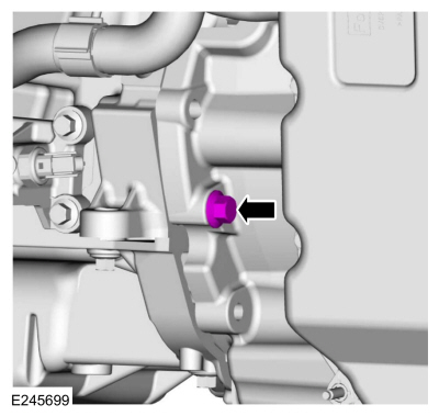
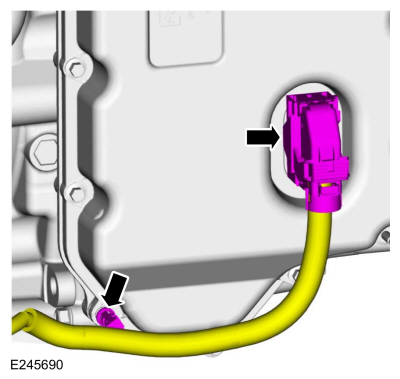
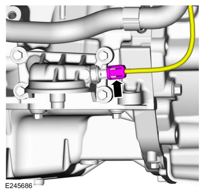
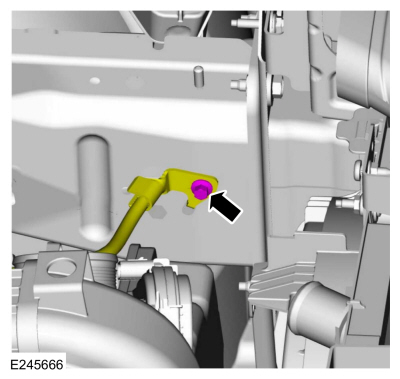
Connect the oil pressure switch wiring harness electrical connector.
-
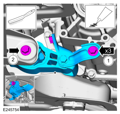
NOTE:
Clean the bolts using a wire brush and apply Motorcraft® Threadlock and Sealer to the threads.
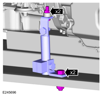
Install the roll restrictor, bolts and tighten the bolts.
-
Material: Motorcraft® Threadlock and Sealer
/ TA-25-B
Torque:
59 lb.ft (80 Nm)
-
Material: Motorcraft® Threadlock and Sealer
/ TA-25-B
Torque:
63 lb.ft (86 Nm)
-
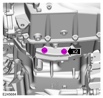
Install the transmission-to-oil pan bolts.
Torque:
35 lb.ft (48 Nm)
-
Install the oil pan-to-transmission stud bolt and bolt.
Torque:
35 lb.ft (48 Nm)
-
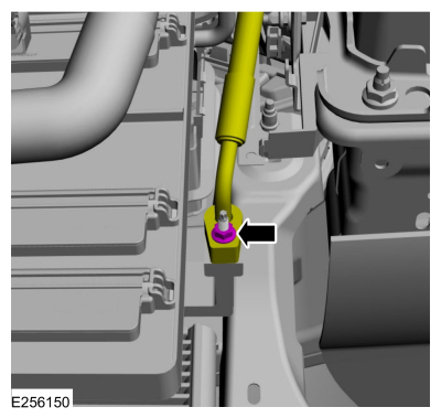
Position the ground wire and install the nut.
Torque:
177 lb.in (20 Nm)
-
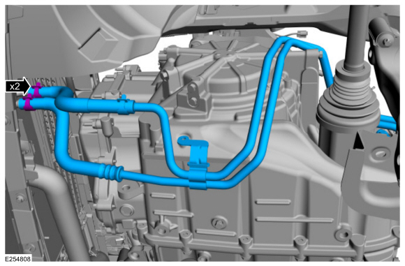
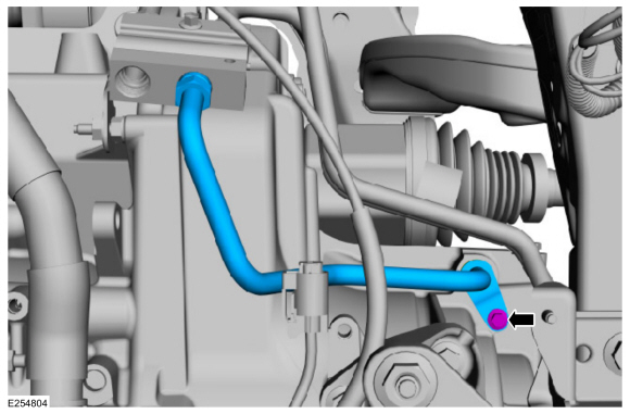
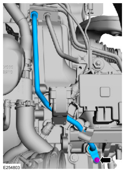
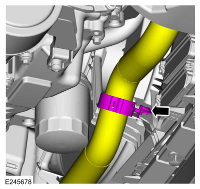
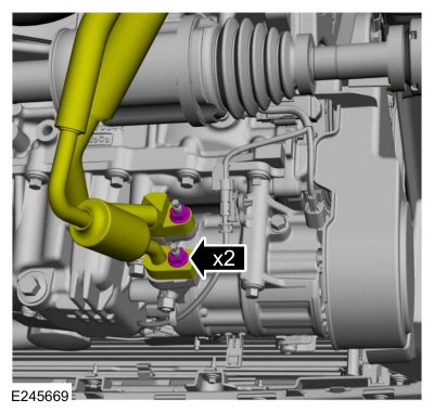
Install the transmission fluid cooler tubes and position the clamps.
-
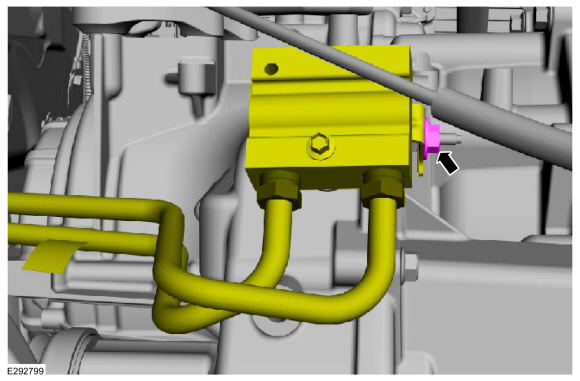
Install the cooler bypass valve nut.
Torque:
80 lb.in (9 Nm)
-
Install the transmission fluid cooler tubes bracket bolt.
Torque:
89 lb.in (10 Nm)
-
-
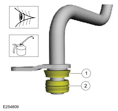
NOTE:
Lubricate the seal and backing ring with clean transmission fluid.
Inspect the transmission fluid tube seal for damage and install new seal if necessary.
Material: Motorcraft® MERCON® LV Automatic Transmission Fluid
/ XT-10-QLVC
(WSS-M2C938-A)
(MERCON® LV, )
-
Inspect the transmission fluid tube backing ring for damage and install new backing ring if necessary.
-
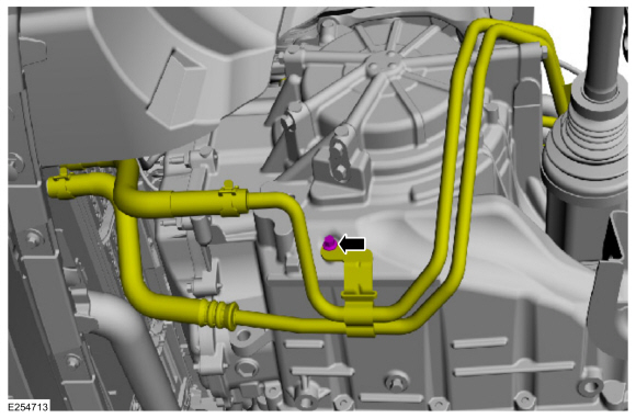
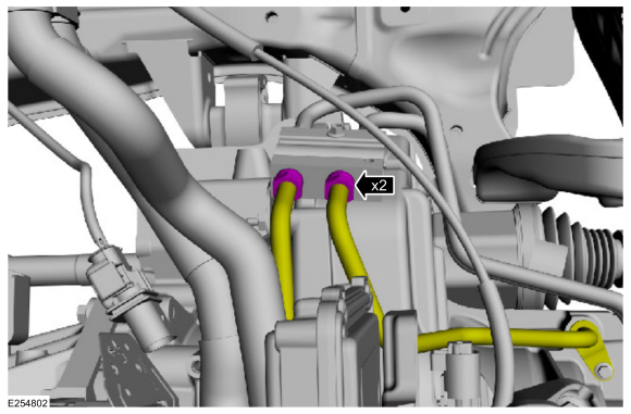
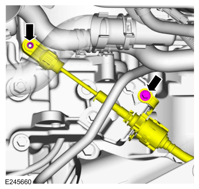
Install the cooler bypass valve-to-transmission fluid tube and the bolt.
Torque:
89 lb.in (10 Nm)
-
-
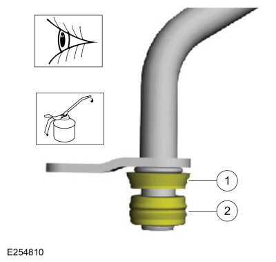
NOTE:
Lubricate the seal and backing ring with clean transmission fluid.
Inspect the transmission fluid tube seal for damage and install new seal if necessary.
Material: Motorcraft® MERCON® LV Automatic Transmission Fluid
/ XT-10-QLVC
(WSS-M2C938-A)
(MERCON® LV, )
-
Inspect the transmission fluid tube backing ring for damage and install new backing ring if necessary.
-
Install the transmission-to-cooler bypass valve tube and the bolt.
Torque:
89 lb.in (10 Nm)
-
Tighten the transmission fluid cooler tubes fittings to the cooler bypass valve.
Torque:
22 lb.ft (30 Nm)
-
Install the LH and RH halfshafts.
Refer to: Front Halfshaft LH - 6-Speed Automatic Transmission – 6F35 (205-04 Front Drive Halfshafts, Removal and Installation).
Refer to: Front Halfshaft RH - 2.0L Duratec-HE (125kW/170PS) – MI4, FWD
(205-04 Front Drive Halfshafts, Removal and Installation).
All Wheel Drive (AWD) vehicles
-
Install the LH halfshaft.
Refer to: Front Halfshaft LH - 6-Speed Automatic Transmission – 6F35 (205-04 Front Drive Halfshafts, Removal and Installation).
-
Install the transfer case.
Refer to: Transfer Case (308-07B Transfer Case - 6-Speed Automatic Transmission – 6F35, Installation).
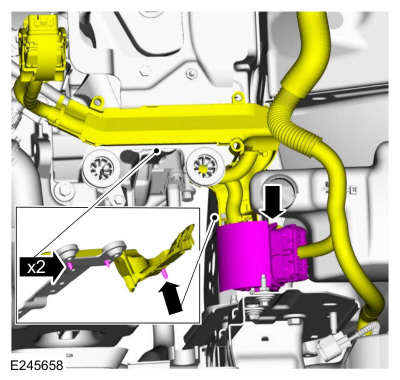
Engine mounted evaporative emission canister purge valve
-
-
Install the EVAP canister purge valve and the nuts.
Torque:
97 lb.in (11 Nm)
-
Connect the EVAP canister purge valve quick connect couplings.
Refer to: Quick Release Coupling (310-00 Fuel System - General Information)
.
-
Connect the EVAP canister purge valve wiring harness electrical connector.
All vehicles
-
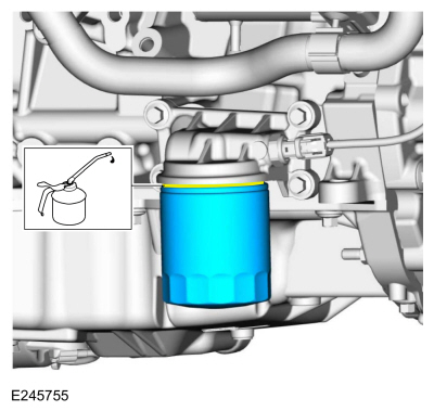
NOTE:
Lubricate the engine oil filter gasket with clean engine oil prior to installing the oil filter.
Install a new engine oil filter.
Refer to: Specifications (303-01C Engine - 2.0L Duratec-HE (129kW/175PS), Specifications).
Torque:
Stage 1:
71 lb.in (8 Nm)
Stage 2:
180°
-
Install the coolant fan motor and shroud.
Refer to: Cooling Fan Motor and Shroud (303-03C Engine Cooling - 2.0L Duratec-HE (129kW/175PS), Removal and Installation).
-
Attach the lower radiator coolant hose retainer to the coolant fan motor and shroud.
-
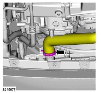
Install the lower radiator coolant hose.
Use the General Equipment: Hose Clamp Remover/Installer
-
-
Remove the support and position the catalytic converter onto the studs.
-
Install the new nuts and tighten in sequence shown.
Torque:
Stage 1:
Tighten:
41 lb.ft (55 Nm)
Stage 2:
Retighten:
41 lb.ft (55 Nm)
-
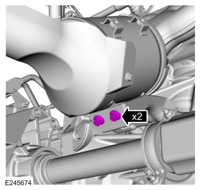
Install the bolts for the catalytic converter support bracket.
Torque:
18 lb.ft (25 Nm)
-
NOTICE:
Make sure that the exhaust flexible pipe is not forcibly bent or twisted.
Remove the catalytic converter support.
-
-
Attach the muffler and tailpipe hanger.
-
Connect and tighten the catalytic converter-to-muffler and tailpipe nut.
Torque:
177 lb.in (20 Nm)
-
NOTE:
Typical catalytic converter shown, sensor position may vary by application.
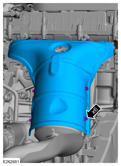
Install the catalytic converter heat shield and the bolts.
Torque:
89 lb.in (10 Nm)
-
Install the following items:
-
Install the catalyst monitor sensor.
Refer to: Catalyst Monitor Sensor (303-14C Electronic Engine Controls -
2.0L Duratec-HE (129kW/175PS), Removal and Installation).
-
Install the HO2S .
Refer to: Heated Oxygen Sensor (HO2S) (303-14C Electronic Engine
Controls - 2.0L Duratec-HE (129kW/175PS), Removal and Installation).
-
Install the A/C compressor belt.
Refer to: Air Conditioning (A/C) Compressor Belt (303-05C Accessory
Drive - 2.0L Duratec-HE (129kW/175PS), Removal and Installation).
-
Install the RH fender splash shield.
Refer to: Fender Splash Shield (501-02 Front End Body Panels, Removal and Installation).
-
-
Uncover the covered ports.
-
Install and lubricate new O-ring seals.
Material: Motorcraft® R-1234yf Refrigerant PAG Oil
/ YN-35
(WSS-M2C300-A2)
-
Install the A/C line and the nut.
Torque:
159 lb.in (18 Nm)
-
Install the A/C line support bracket nut.
Torque:
27 lb.in (3 Nm)
-
-
Uncover the covered ports.
-
Install and lubricate new O-ring seals.
Material: Motorcraft® R-1234yf Refrigerant PAG Oil
/ YN-35
(WSS-M2C300-A2)
-
Install the A/C line and the nut.
Torque:
159 lb.in (18 Nm)
-
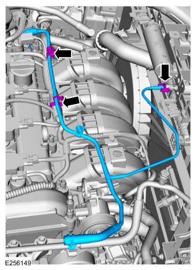
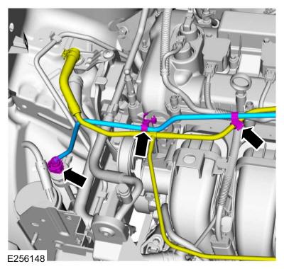
Connect the A/C pressure switch wiring harness electrical connector.
-
Attach the A/C line retainers.
-
-
Uncover the covered ports.
-
Position the A/C line and install the nut.
Torque:
159 lb.in (18 Nm)
-
-
Uncover the covered ports.
-
Install new O-ring seals.
-
Position the A/C lines and install the nuts.
Torque:
159 lb.in (18 Nm)
-
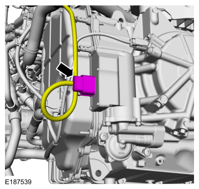
Connect the transmission fluid auxiliary pump electrical connector.
-
Connect the transmission TSS sensor wiring harness electrical connector and retainer.
-
Position the ground cable and install the bolt.
Torque:
106 lb.in (12 Nm)
-
-
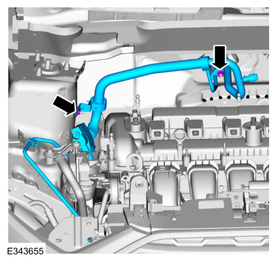
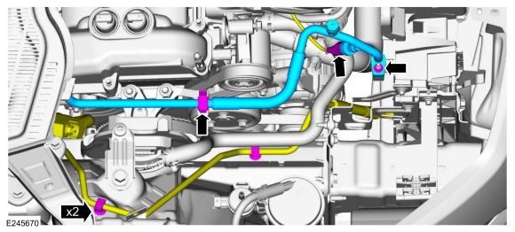
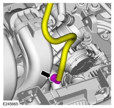
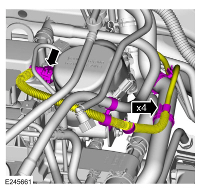
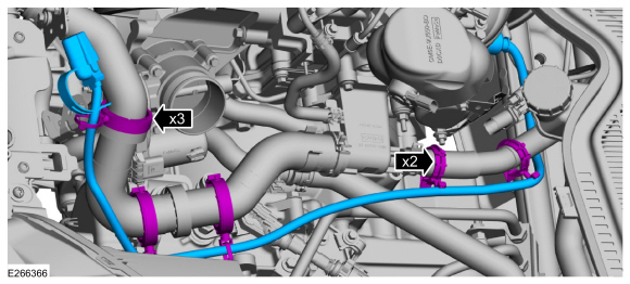
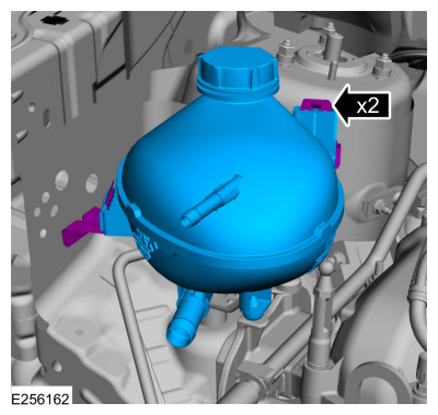
Install the degas bottle coolant tube and attach the pinch clamp to the radiator.
-
Attach the degas bottle coolant tube retainers.
-
-
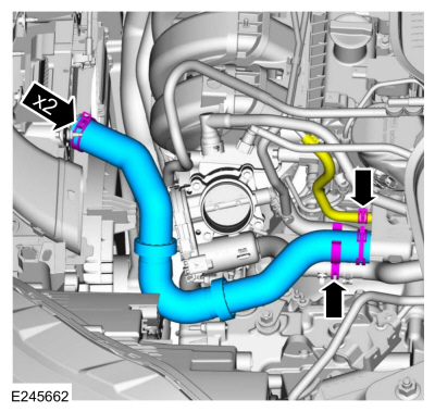
If equipped, install the EVAP canister purge valve tube and connect quick release coupling.
Refer to: Quick Release Coupling (310-00 Fuel System - General Information)
.
-
If equipped, attach the EVAP canister purge valve tube retainers.
All vehicles
-
-
If equipped, connect the EVAP canister purge valve tube quick release coupling to the intake manifold.
Refer to: Quick Release Coupling (310-00 Fuel System - General Information)
.
-
If equipped, attach the EVAP canister purge valve tube retainers.
-
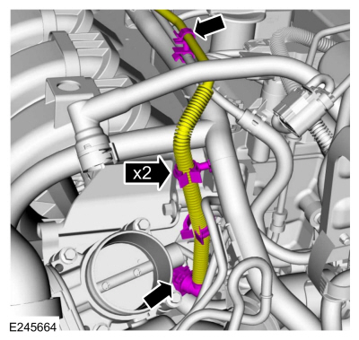
Connect the brake vacuum tube to the intake manifold.
-
Connect the coolant hoses to the heater core.
-
-
Position the degas bottle hose and install the clamp.
Use the General Equipment: Hose Clamp Remover/Installer
-
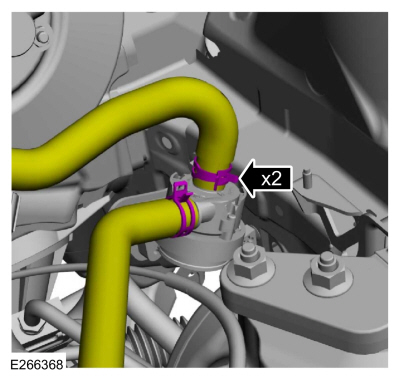
Install the upper radiator hose, retainers and the clamps.
Use the General Equipment: Hose Clamp Remover/Installer
-
Connect the fuel tube quick release coupling and the retainers.
Refer to: Quick Release Coupling (310-00 Fuel System - General Information)
.
-
-
Position the shift cable and install the bolt.
Torque:
89 lb.in (10 Nm)
-
Connect the selector lever cable end to the manual control lever.
-
If equipped, install and attach the block heater wiring harness retainers.
-
If equipped, connect the block heater wiring harness electrical connector.
-
If equipped cabin heater coolant pump, connect the coolant hoses.
Use the General Equipment: Hose Clamp Remover/Installer
-
Install the battery tray bracket and the nuts.
Torque:
89 lb.in (10 Nm)
-
-
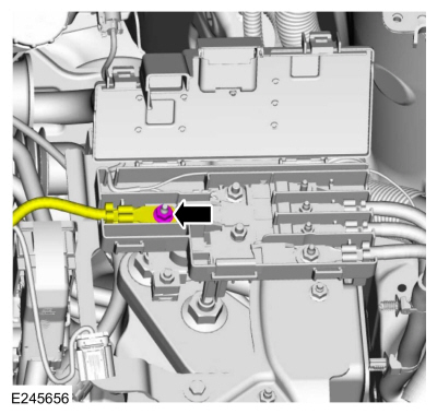
Connect the engine harness wiring connector.
-
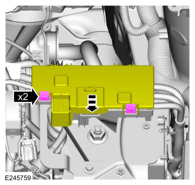
Attach the plastic housing to battery tray bracket.
-
Attach the wire harness retainers to the plastic housing on battery tray bracket.
-
Install the battery feed wire and nut to junction box.
Torque:
106 lb.in (12 Nm)
-
Close the junction box cover and attach tabs.
-
Install the degas bottle on the tabs.
-
-
Install the coolant hoses to the degas bottle.
Use the General Equipment: Hose Clamp Remover/Installer
-
Attach the coolant hose retainer.
-
Install the following items:
-
Install the battery tray.
Refer to: Battery Tray (414-01 Battery, Mounting and Cables, Removal and Installation).
-
Install the RH headlight assembly.
Refer to: Headlamp Assembly (417-01 Exterior Lighting, Removal and Installation).
-
NOTE:
Lubricating the grommets with silicone grease will
aid in the installation of the engine appearance cover, and any future
removal and installation of the cover.
-
Lubricate each grommet with silicone grease.
Material: Motorcraft® Silicone Brake Caliper Grease and Dielectric Compound
/ XG-3-A
(ESA-M1C200-A)
(ESE-M1C171-A)
-
Position the engine appearance cover onto engine with the grommets aligned with the studs.
-
Press down on the engine appearance cover at each grommet location to attach the grommets onto the studs.
-
Fill the engine with clean engine oil.
Refer to: Specifications (303-01C Engine - 2.0L Duratec-HE (129kW/175PS), Specifications).
-
Recharge the A/C system.
Refer to: Air Conditioning (A/C) System Recovery, Evacuation and
Charging - Vehicles With: R1234YF Refrigerant (412-00 Climate Control
System - General Information, General Procedures).
Refer to: Air Conditioning (A/C) System Recovery, Evacuation and
Charging - Vehicles With: R134A Refrigerant (412-00 Climate Control
System - General Information, General Procedures).
-
Adjust the selector lever cable.
Refer to: Selector Lever Cable Adjustment - 6-Speed Automatic
Transmission – 6F35 (307-05 Automatic Transmission External Controls,
General Procedures).
-
Install the air cleaner.
Refer to: Air Cleaner (303-12C Intake Air Distribution and Filtering -
2.0L Duratec-HE (129kW/175PS), Removal and Installation).
-
Fill and bleed the cooling system.
Refer to: Engine Cooling System Draining, Vacuum Filling and Bleeding
(303-03C Engine Cooling - 2.0L Duratec-HE (129kW/175PS), General
Procedures).
-
Check the transmission fluid level.
Refer to: Transmission Fluid Level Check (307-01B Automatic
Transmission - 6-Speed Automatic Transmission – 6F35, General
Procedures).
-
Start and check the exhaust system for leaks.
-
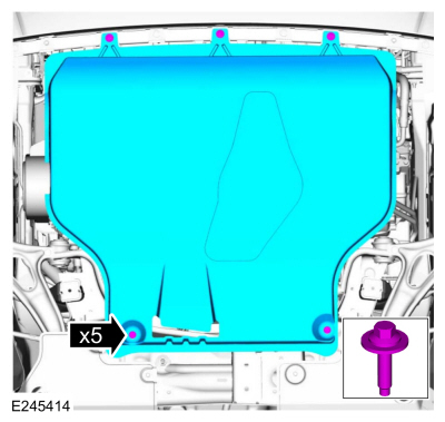
If equipped, install the underbody shield and the bolts.
-
Use the Powertrain Control Module (PCM) Misfire Monitor Profile Correction routine in the diagnostic scan tool.
Other information:
Removal
NOTE:
Removal steps in this procedure may contain installation details.
Remove the RH steering wheel multifunction switch.
Refer to: Steering Wheel Multifunction Switch (211-05 Steering Wheel
and Column Electrical Components, Removal and Installation).
Disconnect the downshift paddle switch electrical connector.
..
Special Tool(s) /
General Equipment
Long Nose Pliers
Removal
Using the scan tool Transmission Solenoid Identification
Number (IDN) function, retrieve the solenoid base part number and
stamping number.
Remove the transmission internal wiring harness frame.
Refer to: Transmission Internal Wiring Harness Frame (307-0..