Ford Ecosport: Engine - 2.0L Duratec-HE (129kW/175PS) / Removal - Engine
Special Tool(s) /
General Equipment
 |
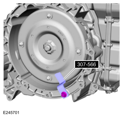
307-566
Retainer, Torque Converter
TKIT-2006C-FFMFLM
TKIT-2006C-LM
TKIT-2006C-ROW |
| Magnetic Socket |
| Floor Crane |
| Adjustable Mounting Arm |
| Oil Drain Equipment |
| Cable Ties |
| Hose Clamp Remover/Installer |
| Powertrain Jack |
| Wooden Block |
All vehicles
-
With the vehicle in NEUTRAL, position it on a hoist.
Refer to: Jacking and Lifting - Overview (100-02 Jacking and Lifting, Description and Operation).
-
NOTICE:
Do not pull the engine appearance cover forward or
sideways to remove. Failure to press straight upward on the underside of
the cover at the attachment points may result in damage to the cover or
engine components.
-
Place your hand under the engine appearance cover at
each grommet location and push straight up to release each grommet from
the studs.
-
After all of the grommets have been released from the studs, remove the appearance cover from the engine.
-
Evacuate the A/C system.
Refer to: Air Conditioning (A/C) System Recovery, Evacuation and
Charging - Vehicles With: R1234YF Refrigerant (412-00 Climate Control
System - General Information, General Procedures).
Refer to: Air Conditioning (A/C) System Recovery, Evacuation and
Charging - Vehicles With: R134A Refrigerant (412-00 Climate Control
System - General Information, General Procedures).
-
Release the fuel system pressure.
Refer to: Fuel System Pressure Release (310-00C Fuel System - General
Information - 2.0L Duratec-HE (129kW/175PS), General Procedures).
-
If equipped, remove the bolts and the underbody shield.
-
Drain the cooling system.
Refer to: Engine Cooling System Draining, Vacuum Filling and Bleeding
(303-03C Engine Cooling - 2.0L Duratec-HE (129kW/175PS), General
Procedures).
-
Remove the following items:
-
Remove the RH headlight assembly.
Refer to: Headlamp Assembly (417-01 Exterior Lighting, Removal and Installation).
-
Remove the air cleaner.
Refer to: Air Cleaner (303-12C Intake Air Distribution and Filtering -
2.0L Duratec-HE (129kW/175PS), Removal and Installation).
-
Remove the battery tray.
Refer to: Battery Tray (414-01 Battery, Mounting and Cables, Removal and Installation).
-
-
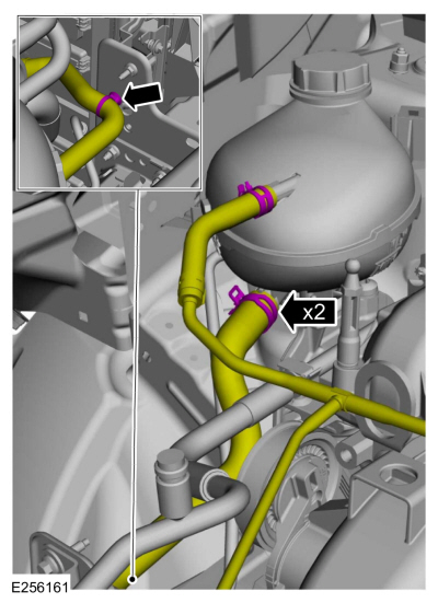
Detach the coolant hose retainer.
-
Remove the coolant hoses from the degas bottle.
Use the General Equipment: Hose Clamp Remover/Installer
-
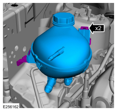
Release the tabs and remove the degas bottle.
-
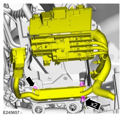
Release the tabs and open the junction box cover.
-
Remove the nut and the battery feed wiring harness from the junction box.
-
Separate and detach the wire harness retainers from the plastic housing on battery tray bracket.
-
-
Detach the plastic housing from battery tray bracket.
-
Disconnect the engine harness connector.
-
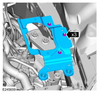
Remove the nuts and the battery tray bracket.
-
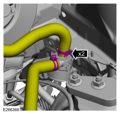
If equipped cabin heater coolant pump, disconnect the coolant hoses.
Use the General Equipment: Hose Clamp Remover/Installer
-
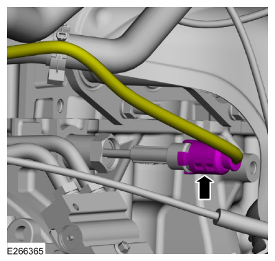
If equipped, disconnect the block heater wiring harness electrical connector.
-
If equipped, detach the block heater wiring harness retainers and remove.
-
-
Disconnect the selector lever cable end from the manual control lever.
-
Remove the bolt and position the shift cable aside.
-
Disconnect the fuel tube quick release coupling and the retainers.
Refer to: Quick Release Coupling (310-00 Fuel System - General Information)
.
-
-
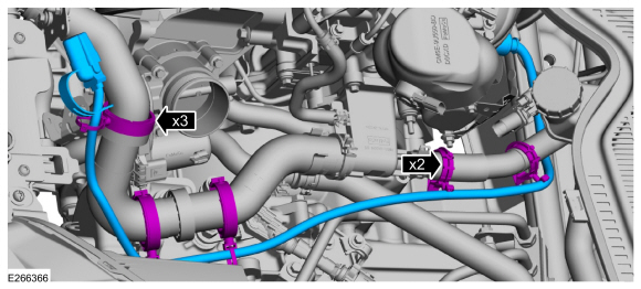
Detach the retainer and release the clamps and remove the upper radiator hose.
Use the General Equipment: Hose Clamp Remover/Installer
-
Release the clamp and position the degas bottle hose aside.
Use the General Equipment: Hose Clamp Remover/Installer
-
Disconnect the coolant hoses from the heater core.
-
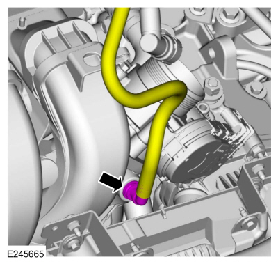
Disconnect the brake vacuum tube from the intake manifold.
Engine mounted evaporative emission canister purge valve
-
-
Disconnect the EVAP canister purge valve wiring harness electrical connector.
-
Disconnect the EVAP canister purge valve quick connect couplings.
Refer to: Quick Release Coupling (310-00 Fuel System - General Information)
.
-
Remove the nuts and the EVAP canister purge valve.
All vehicles
-
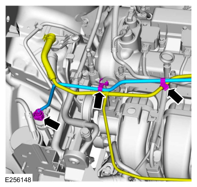
-
If equipped, disconnect the EVAP canister purge valve tube quick release coupling from the intake manifold.
Refer to: Quick Release Coupling (310-00 Fuel System - General Information)
.
-
If equipped, release the EVAP canister purge valve tube retainers.
-
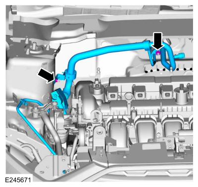
-
If equipped, release the EVAP canister purge valve tube retainers.
-
If equipped, disconnect the EVAP canister purge valve tube quick
release coupling and remove the EVAP canister purge valve tube.
Refer to: Quick Release Coupling (310-00 Fuel System - General Information)
.
-
-
Release the degas bottle coolant tube retainers.
-
Release the pinch clamp and remove the degas bottle coolant tube from the radiator.
-
Remove the bolt from side rail and position the ground cable aside.
-
Disconnect the transmission TSS sensor wiring harness electrical connector and retainer.
-
Disconnect the transmission fluid auxiliary pump electrical connector.
-
NOTICE:
During the removal of components, cap, tape or
otherwise appropriately protect all openings to prevent the ingress of
dirt or other contamination. Remove protective materials prior to
installation.
-
Remove the nuts and position the A/C lines aside.
-
Discard the O-ring seals.
-
Make sure to cover any open ports to prevent debris from entering the system.
-
NOTICE:
During the removal of components, cap, tape or
otherwise appropriately protect all openings to prevent the ingress of
dirt or other contamination. Remove protective materials prior to
installation.
-
Remove the nut and position the A/C line aside.
-
Make sure to cover any open ports to prevent debris from entering the system.
-
NOTICE:
During the removal of components, cap, tape or
otherwise appropriately protect all openings to prevent the ingress of
dirt or other contamination. Remove protective materials prior to
installation.
-
Detach the A/C line retainers.
-
Disconnect the A/C pressure switch wiring harness electrical connector.
-
Remove the nut and the A/C line.
-
Make sure to cover any open ports to prevent debris from entering the system.
-
NOTICE:
During the removal of components, cap, tape or
otherwise appropriately protect all openings to prevent the ingress of
dirt or other contamination. Remove protective materials prior to
installation.
-
Remove the nuts and the A/C line.
-
Make sure to cover any open ports to prevent debris from entering the system.
-
Remove the following items:
-
Remove the RH fender splash shield.
Refer to: Fender Splash Shield (501-02 Front End Body Panels, Removal and Installation).
-
Remove the A/C compressor belt.
Refer to: Air Conditioning (A/C) Compressor Belt (303-05C Accessory
Drive - 2.0L Duratec-HE (129kW/175PS), Removal and Installation).
-
Remove the HO2S .
Refer to: Heated Oxygen Sensor (HO2S) (303-14C Electronic Engine
Controls - 2.0L Duratec-HE (129kW/175PS), Removal and Installation).
-
Remove the catalyst monitor sensor.
Refer to: Catalyst Monitor Sensor (303-14C Electronic Engine Controls -
2.0L Duratec-HE (129kW/175PS), Removal and Installation).
-
NOTE:
Typical catalytic converter shown, sensor position may vary by application.
Remove the bolts and the catalytic converter heat shield.
-
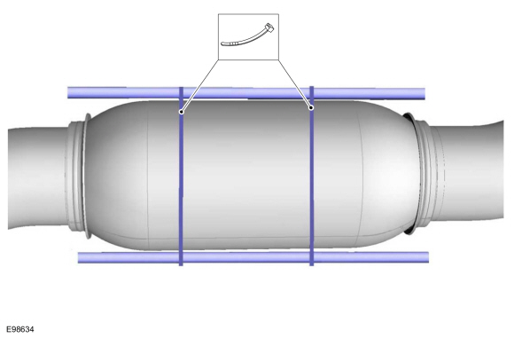
NOTICE:
Make sure that the exhaust flexible pipe is not forcibly bent or twisted.
Support the catalytic converter.
Use the General Equipment: Cable Ties
-
Remove the bolts for the catalytic converter support bracket.
-
NOTE:
Clean the catalytic converter-to-muffler sealing surfaces.
-
Loosen the catalytic converter-to-muffler and tailpipe nut and separate.
-
Detach the muffler and tailpipe hanger.
-
-
Remove and discard the nuts.
-
Position the catalytic converter aside and support.
-
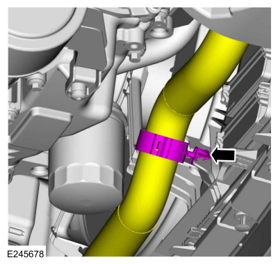
Release the clamp and remove the lower radiator coolant hose.
Use the General Equipment: Hose Clamp Remover/Installer
-
Detach the lower radiator coolant hose retainer from the coolant fan motor and shroud.
-
Remove the coolant fan motor and shroud.
Refer to: Cooling Fan Motor and Shroud (303-03C Engine Cooling - 2.0L Duratec-HE (129kW/175PS), Removal and Installation).
-
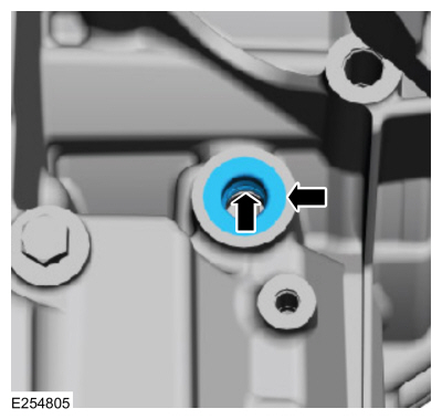
-
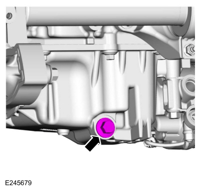
Remove the drain plug and drain the engine oil.
Use the General Equipment: Oil Drain Equipment
-
Install drain plug.
Torque:
20 lb.ft (27 Nm)
-
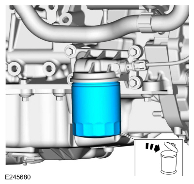
Remove and discard the engine oil filter.
Use the General Equipment: Oil Drain Equipment
All Wheel Drive (AWD) vehicles
-
Remove the transfer case.
Refer to: Transfer Case (308-07B Transfer Case - 6-Speed Automatic Transmission – 6F35, Removal).
-
Remove the LH halfshaft.
Refer to: Front Halfshaft LH - 6-Speed Automatic Transmission – 6F35 (205-04 Front Drive Halfshafts, Removal and Installation).
All vehicles
-
Remove the LH and RH halfshafts.
Refer to: Front Halfshaft LH - 6-Speed Automatic Transmission – 6F35 (205-04 Front Drive Halfshafts, Removal and Installation).
Refer to: Front Halfshaft RH - 2.0L Duratec-HE (125kW/170PS) – MI4, FWD
(205-04 Front Drive Halfshafts, Removal and Installation).
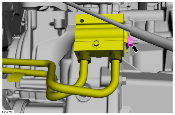
-
NOTE:
Be prepared to collect escaping fluid.
Completely loosen the transmission fluid cooler tubes fittings from the cooler bypass valve.
-
NOTE:
Be prepared to collect escaping fluid.
Remove the bolt and the transmission-to-cooler bypass valve tube.
-
Inspect the transmission to be sure the transmission
fluid tube seal and backing ring were removed with the transmission
fluid tube and are not stuck in the transmission. If the transmission
fluid tube seal or backing ring is stuck in the transmission, remove the
seal and backing ring.
-
NOTE:
Be prepared to collect escaping fluid.
Remove the bolt and the cooler bypass valve-to-transmission fluid tube.
-
Inspect the transmission to be sure the transmission
fluid tube seal and backing ring were removed with the transmission
fluid tube and are not stuck in the transmission. If the transmission
fluid tube seal or backing ring is stuck in the transmission, remove the
seal and backing ring.
-
Remove the transmission fluid cooler tubes bracket bolt.
-
Remove the cooler bypass valve nut.
-
NOTE:
Be prepared to collect escaping fluid.
Release the clamps and remove the transmission fluid cooler tubes.
-
Remove the nut and position the ground wire aside.
-
Remove the oil pan-to-transmission stud bolt and bolt.
-
Remove the transmission-to-oil pan bolts.
-
Remove the bolts and the engine roll restrictor.
-
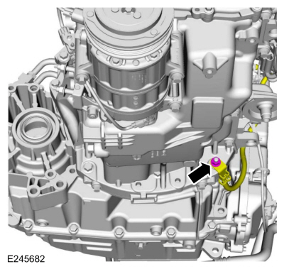
NOTE:
The oil pressure switch needs to be disconnected to install adjustable mounting arm.
Disconnect the oil pressure switch wiring harness electrical connector.
-
-
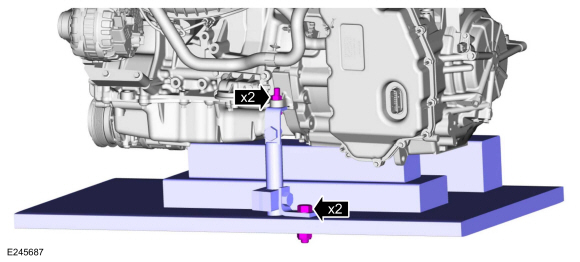
Position the powertrain jack and boards under the engine and transmission.
Use the General Equipment: Powertrain Jack
Use the General Equipment: Wooden Block
-
Install adjustable mounting arm.
Use the General Equipment: Adjustable Mounting Arm
-
-
Remove the nuts, bolts and the engine mount.
-
Discard the nuts and bolts.
-
Remove the transmission mount bolts.
-
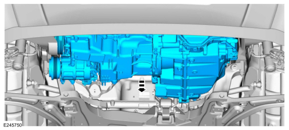
Lower the powertrain from the vehicle.
-
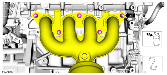
Remove and discard the catalytic converter manifold stud bolts and gasket.
-
Clean and inspect the catalytic converter manifold.
Refer to: Exhaust Manifold Cleaning and Inspection (303-00 Engine System - General Information, General Procedures).
-
Disconnect the transmission wiring harness electrical connector and retainer.
-
-
Detach the coolant hose retainer.
-
Detach the wiring harness retainers.
-
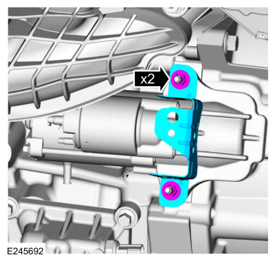
Remove the nuts and the starter motor bracket.
-
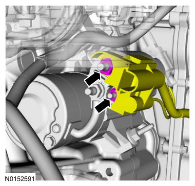
Remove the nuts and disconnect starter motor battery positive cable and motor control wire housing.
-
Remove the stud bolts and the starter motor.
-
Remove the starter motor isolator.
-
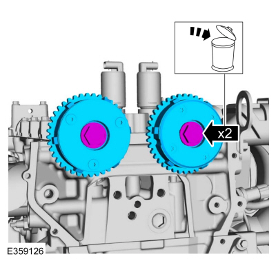
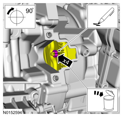
NOTICE:
Rotate the engine in a clockwise direction only or engine damage may occur.
NOTE:
Note the position of the components before removal.
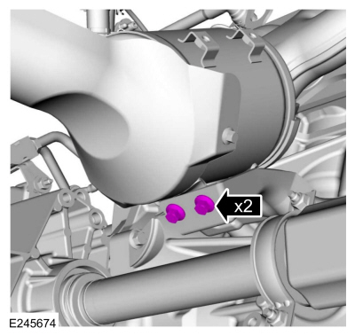
Remove the torque converter nuts and discard.
Use the General Equipment: Magnetic Socket
-
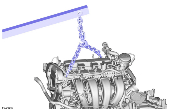
Install the floor crane and engine lift equipment.
Use the General Equipment: Floor Crane
-
Remove adjustable mounting arm.
Use the General Equipment: Adjustable Mounting Arm
-
Remove the engine-to-transmission bolts.
-
Remove the transmission-to-engine bolts.
-
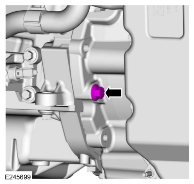
Remove the transmission-to-engine bolt.
-
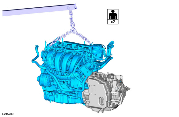
Using the floor crane and engine lift equipment, separate the engine from the transmission.
Use the General Equipment: Floor Crane
-
Install Special Service Tool: 307-566
Retainer, Torque Converter.
Removal
NOTICE:
During engine repair procedures, cleanliness is extremely
important. Any foreign material, including any material created while
cleaning gasket surfaces, that enters the oil passages, coolant passages
or the oil pan can cause engine failure...
Special Tool(s) /
General Equipment
205-153
(T80T-4000-W)
Handle
303-103
(T74P-6375-A)
Holding Tool, FlywheelT74P-77000-ATKIT-2009TC-F
303-1247VCT Spark Plug Tube Seal Remover and InstallerTKIT-2006UF-FLMTKIT-2006UF-ROW
303-1565Alignment Tool, CamshaftTKIT-2010C-FLM
303-409
(T92C-6700-CH)
Remover, Crankshaft SealTKIT-1992-FH/FMH/F..
Other information:
Special Tool(s) /
General Equipment
Resistance Spotwelding Equipment
Hot Air Gun
Air Body Saw
MIG/MAG Welding Equipment
Spot Weld Drill Bit
Locking Pliers
Removal
Remove the front door.
Refer to: Front Door (501-03 Body Closures, Removal and Installation).
Remove the rear door.
Refer to: Rear Door (..
Overview
The perimeter anti-theft alarm system has three operation modes:
ARMED - The perimeter anti-theft alarm is armed when the
ignition is OFF and all vehicle entry points have been electrically
locked for 20 seconds.
ACTIVE - When the perimeter anti-theft alarm activates,
the horn sounds and all turn signals and interior courtesy lamps flash.
The horn stops soundin..


 Removal and Installation - Variable Camshaft Timing (VCT) Unit
 Disassembly - Engine