Ford Ecosport: Climate Control System - General Information / Removal and Installation - Thermostatic Expansion Valve
Removal
NOTICE: During the removal of components, cap, tape or otherwise appropriately protect all openings to prevent the ingress of dirt or other contamination. Remove protective materials prior to installation.
NOTE: Removal steps in this procedure may contain installation details.
-
Recover the refrigerant.
Refer to: Air Conditioning (A/C) System Recovery, Evacuation and Charging - Vehicles With: R134A Refrigerant (412-00 Climate Control System - General Information, General Procedures).
-
Remove the engine appearance cover.
 |
-
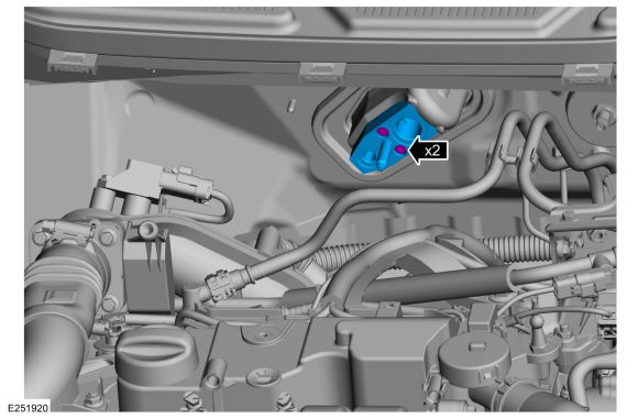
Remove the thermostatic expansion valve nut, disconnect the fitting, remove the support brace retainer and position aside.
-
Make sure to cover any open ports to prevent debris from entering the system.
Torque:
thermostatic expansion valve nut: 133 lb.in (15 Nm)
support bracket: 27 lb.in (3 Nm)
-
Make sure to cover any open ports to prevent debris from entering the system.
 |
-
Remove the thermostatic expansion valve bolts and the thermostatic expansion valve.
-
Make sure to cover any open ports to prevent debris from entering the system.
Torque: 71 lb.in (8 Nm)
-
Make sure to cover any open ports to prevent debris from entering the system.
 |
Installation
-
To install, reverse the removal procedure.
-
NOTICE: Only use the specified material to lubricate the seals.
Install and lubricate new O-ring seals.
-
Lubricate the refrigerant system with the correct amount
of clean PAG oil. Refer to the appropriate Refrigerant Oil Adding
procedure in Group 412.
 Removal and Installation - Temperature Door Actuator
Removal
NOTE:
Removal steps in this procedure may contain installation details.
Remove the climate control housing.
Refer to: Climate Control Housing (412-00 Climate Control System - General Information, Removal and Installation)...

Other information:
Ford Ecosport 2014-2025 Service and Repair Manual: Removal and Installation - All-Wheel Drive (AWD) Module
Removal NOTE: Removal steps in this procedure may contain installation details. NOTE: Position aside the RH side front seat Move the seat to back position. Detach the floor from the main floor and position aside. Remove the 2 bolts from the front floor ffirst ..
Ford Ecosport 2014-2025 Service and Repair Manual: Removal and Installation - Transmission Fluid Cooler
Removal NOTE: Removal steps in this procedure may contain installation details. Refer to: Radiator (303-03B Engine Cooling - 1.5L Duratec (90kW/120PS) – I3, Removal and Installation). Refer to: Radiator (303-03C Engine Cooling - 2.0L Duratec-HE (129kW/175PS), Removal and Installation). Remove the bolts and the transmission fluid cooler. To..
Categories
- Manuals Home
- 2nd Gen Ford Ecosport Service Manual (2014 - 2025)
- Removal and Installation - Fuel Pump and Sender Unit
- Removal and Installation - Body Control Module (BCM)
- Removal and Installation - Block Heater
- Removal and Installation - Front Seat
- Description and Operation - Evaporative Emissions - System Operation and Component Description
Removal and Installation - Front Stabilizer Bar
Special Tool(s) / General Equipment
Tie Rod End Remover Transmission JackRemoval
NOTICE: Suspension fasteners are critical parts that affect the performance of vital components and systems. Failure of these fasteners may result in major service expense. Use the same or equivalent parts if replacement is necessary. Do not use a replacement part of lesser quality or substitute design. Tighten fasteners as specified.
NOTE: Removal steps in this procedure may contain installation details.
NOTICE: Disconnect the b