Ford Ecosport: Engine - 2.0L Duratec-HE (129kW/175PS) / Removal and Installation - Oil Pan
Special Tool(s) /
General Equipment
Materials
| Name |
Specification |
Motorcraft® Threadlock and Sealer
TA-25-B |
-
|
Motorcraft® Silicone Gasket and Sealant
TA-30 |
WSE-M4G323-A4
|
Removal
LHD 4WD/LHD FWD
-
With the vehicle in NEUTRAL, position it on a hoist.
Refer to: Jacking and Lifting - Overview (100-02 Jacking and Lifting, Description and Operation).
-
Remove the oil level indicator.
-
Remove the air cleaner and the air cleaner outlet pipe.
Refer to: Air Cleaner (303-12C Intake Air Distribution and Filtering -
2.0L Duratec-HE (129kW/175PS), Removal and Installation).
Refer to: Air Cleaner Outlet Pipe (303-12C Intake Air Distribution and
Filtering - 2.0L Duratec-HE (129kW/175PS), Removal and Installation).
-
-
Disconnect the selector lever cable end from the manual control lever.
-
Remove the bolt and position aside the shift cable.
-
NOTICE:
To prevent damage to the transmission, do not
loosen the transmission-to-engine bolts more than (0.197 in) 5 mm.
Loosen the bolts.
-
Remove the A/C compressor belt.
Refer to: Air Conditioning (A/C) Compressor Belt (303-05C Accessory
Drive - 2.0L Duratec-HE (129kW/175PS), Removal and Installation).
-
NOTICE:
To prevent damage to the transmission, do not
loosen the transmission-to-engine bolts more than (0.197 in) 5 mm.
Loosen the bolt.
-
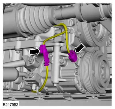
Disconnect the A/C compressor electrical connectors.
-
NOTICE:
Support the A/C compressor. Do not allow the A/C compressor to hang by
the A/C lines or damage to the A/C compressor and tubes may occur.
Remove the bolts and position aside the A/C compressor and support.
-
-
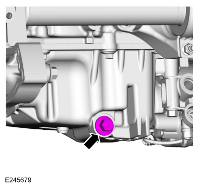
Remove the drain plug and drain the engine oil.
Use the General Equipment: Oil Drain Equipment
-
Install drain plug.
Torque:
20 lb.ft (27 Nm)
-
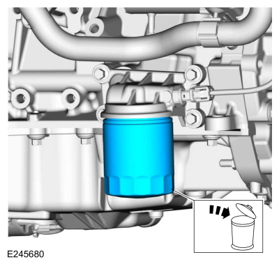
Remove and discard the engine oil filter.
-
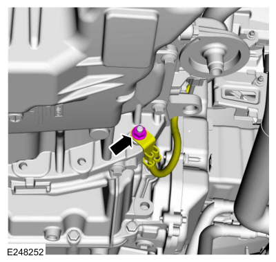
Remove the nut and position the ground cable aside.
-
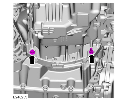
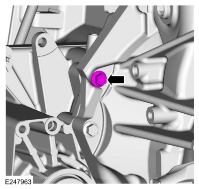
Remove the oil pan bolt and stud bolt.
-
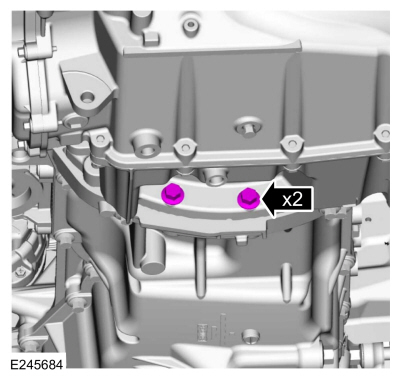
Remove the transmission bolts.
-
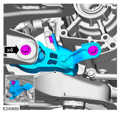
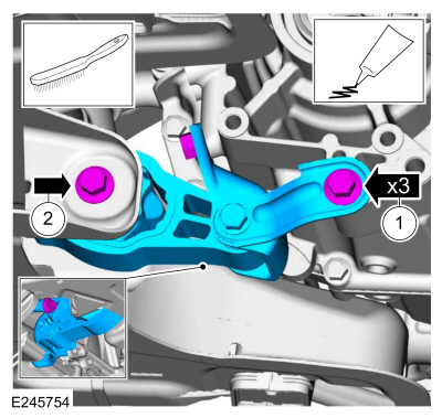
Remove the bolts and the engine roll restrictor.
LHD 4WD
-
Remove the transfer case.
Refer to: Transfer Case (308-07B Transfer Case - 6-Speed Automatic Transmission – 6F35, Removal).
LHD 4WD/LHD FWD
-
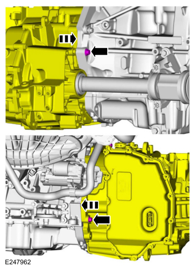
NOTICE:
To prevent damage to the transmission, do not
loosen the engine-to-transmission bolts more than (0.197 in) 5 mm.
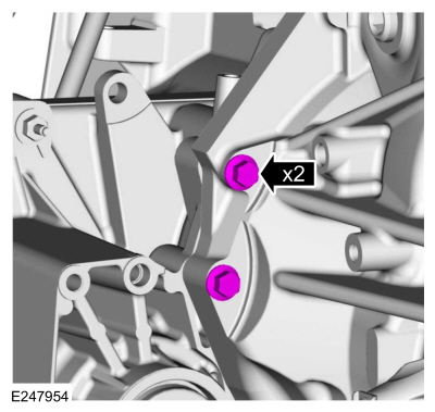
Loosen the bolts.
-
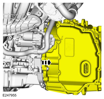
Separate the transmission and engine.
-
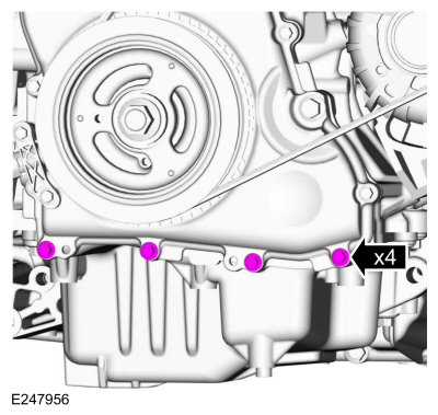
Remove the engine front cover-to-oil pan bolts.
-
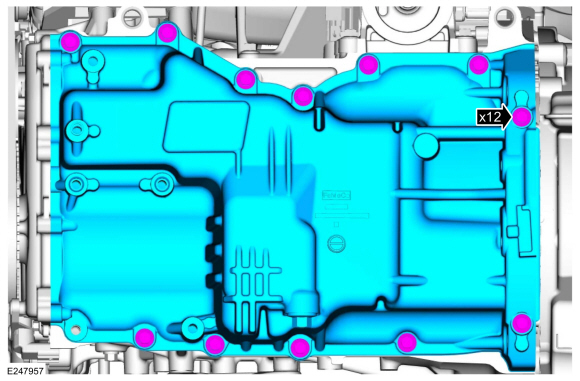
Remove the bolts and the oil pan.
-
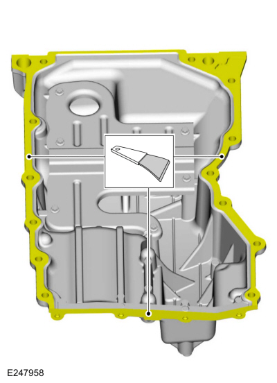
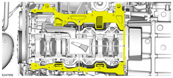
Clean and prepare the RTV sealing surface.
Refer to: RTV Sealing Surface Cleaning and Preparation (303-00 Engine System - General Information, General Procedures).
-
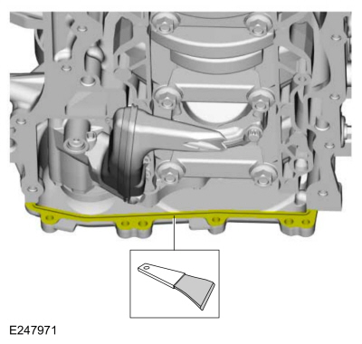
Clean and prepare the RTV sealing surface.
Refer to: RTV Sealing Surface Cleaning and Preparation (303-00 Engine System - General Information, General Procedures).
-
Clean and prepare the RTV sealing surface.
Refer to: RTV Sealing Surface Cleaning and Preparation (303-00 Engine System - General Information, General Procedures).
Installation
LHD 4WD/LHD FWD
-
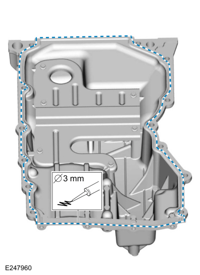
NOTE:
If the oil pan is not secured within 10 minutes
of sealant application, the sealant must be removed and the sealing area
cleaned. Allow to dry until there is no sign of wetness, or 10 minutes,
whichever is longer. Failure to follow this procedure can cause future
oil leakage.
Apply a 3 mm bead of silicone sealant.
Material: Motorcraft® Silicone Gasket and Sealant
/ TA-30
(WSE-M4G323-A4)
-
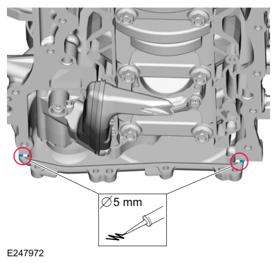
NOTE:
If the oil pan is not secured within 10 minutes
of sealant application, the sealant must be removed and the sealing area
cleaned. Allow to dry until there is no sign of wetness, or 10 minutes,
whichever is longer. Failure to follow this procedure can cause future
oil leakage.
Apply a 5 mm bead of silicone sealant.
Material: Motorcraft® Silicone Gasket and Sealant
/ TA-30
(WSE-M4G323-A4)
-
Install the oil pan and the bolts finger-tight.
-
NOTE:
The engine front cover-to-oil pan fasteners must
be tightened first to align the front surface of the oil pan flush with
the front surface of the engine block.
Install the engine front cover-to-oil pan bolts.
Torque:
89 lb.in (10 Nm)
-
Tighten the bolts in sequence shown.
Torque:
18 lb.ft (25 Nm)
-
NOTE:
Alternate tightening the LH bellhousing-to-engine and RH
engine-to-bellhousing lower bolts to draw the transaxle and engine
together.
Tighten the bolts.
Torque:
35 lb.ft (48 Nm)
-
Tighten the bolt.
Torque:
35 lb.ft (48 Nm)
LHD 4WD
-
Install the transfer case.
Refer to: Transfer Case (308-07B Transfer Case - 6-Speed Automatic Transmission – 6F35, Installation).
LHD 4WD/LHD FWD
-
NOTE:
Clean the bolts using a wire brush and apply Motorcraft® Threadlock and Sealer to the threads.
Install the roll restrictor, bolts and tighten the bolts.
-
Material: Motorcraft® Threadlock and Sealer
/ TA-25-B
Torque:
59 lb.ft (80 Nm)
-
Material: Motorcraft® Threadlock and Sealer
/ TA-25-B
Torque:
63 lb.ft (86 Nm)
-
Install the transmission bolts.
Torque:
35 lb.ft (48 Nm)
-
Install the oil pan bolt and stud bolt.
Torque:
35 lb.ft (48 Nm)
-
Position the ground cable and install the nut.
Torque:
177 lb.in (20 Nm)
-
Remove the support and position the A/C compressor and install the bolts.
Torque:
18 lb.ft (25 Nm)
-
Connect the A/C compressor electrical connectors.
-
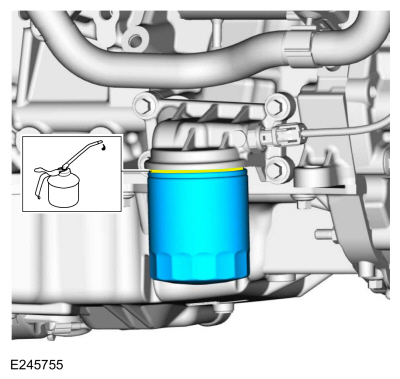
NOTE:
Lubricate the engine oil filter gasket with clean engine oil prior to installing the oil filter.
Install a new engine oil filter.
Torque:
Stage 1:
71 lb.in (8 Nm)
Stage 2:
180°
-
Install the A/C compressor belt.
Refer to: Air Conditioning (A/C) Compressor Belt (303-05C Accessory
Drive - 2.0L Duratec-HE (129kW/175PS), Removal and Installation).
-
Tighten the bolts.
Torque:
35 lb.ft (48 Nm)
-
-
Position the shift cable and install the bolt.
Torque:
89 lb.in (10 Nm)
-
Connect the selector lever cable end to the manual control lever.
-
Install the air cleaner and the air cleaner outlet pipe.
Refer to: Air Cleaner (303-12C Intake Air Distribution and Filtering -
2.0L Duratec-HE (129kW/175PS), Removal and Installation).
Refer to: Air Cleaner Outlet Pipe (303-12C Intake Air Distribution and
Filtering - 2.0L Duratec-HE (129kW/175PS), Removal and Installation).
-
Install the oil indicator.
-
Fill the engine with clean engine oil.
Refer to: Specifications (303-01C Engine - 2.0L Duratec-HE (129kW/175PS), Specifications).
Materials
Name
Specification
Motorcraft® Silicone Brake Caliper Grease and Dielectric CompoundXG-3-A
ESA-M1C200-AESE-M1C171-A
Removal
With the vehicle in NEUTRAL, position it on a hoist...
Materials
Name
Specification
Motorcraft® Thread Sealant with PTFETA-24-B
WSK-M2G350-A2
Removal
NOTE:
Removal steps in this procedure may contain installation details...
Other information:
Removal
NOTE:
Removal steps in this procedure may contain installation details.
Remove the brake pedal and bracket assembly.
Refer to: Brake Pedal and Bracket (206-06 Hydraulic Brake Actuation, Removal and Installation).
Disconnect the electrical connector, remove the retainers and the blower motor...
Overview
Before beginning any service procedure in this manual, refer to health
and safety warnings in section 100-00 General Information. Failure to
follow this instruction may result in serious personal injury.
WARNING:
Before servicing any tire, ask the customer if anyone
injected a tire sealant into the tire...









 Removal and Installation - Intake Manifold
 Removal and Installation - Oil Pressure Switch
 WARNING:
Wear eye and ear protection when servicing a vehicle.
Failure to follow this instruction may result in serious personal
injury.