Ford Ecosport: Engine - 2.0L Duratec-HE (129kW/175PS) / Removal and Installation - Intake Manifold
Materials
| Name |
Specification |
Motorcraft® Silicone Brake Caliper Grease and Dielectric Compound
XG-3-A |
ESA-M1C200-A
ESE-M1C171-A
|
Removal
-
With the vehicle in NEUTRAL, position it on a hoist.
Refer to: Jacking and Lifting - Overview (100-02 Jacking and Lifting, Description and Operation).
-
Disconnect the battery ground.
Refer to: Battery Disconnect and Connect (414-01 Battery, Mounting and Cables, General Procedures).
-
NOTICE:
Do not pull the engine appearance cover forward or
sideways to remove. Failure to press straight upward on the underside of
the cover at the attachment points may result in damage to the cover or
engine components.
-
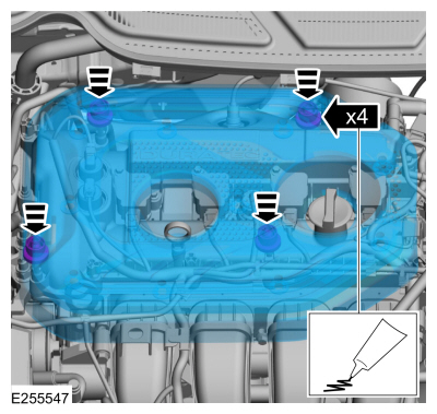
Place your hand under the engine appearance cover at
each grommet location and push straight up to release each grommet from
the studs.
-
After all of the grommets have been released from the studs, remove the appearance cover from the engine.
-
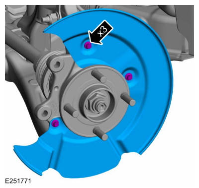
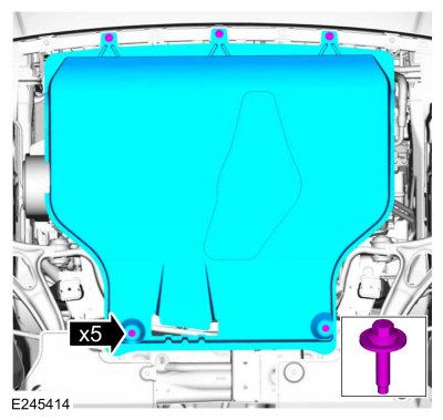
If equipped, remove the bolts and the underbody shield.
-
-
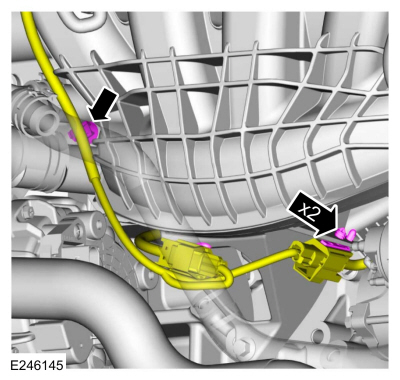
Detach the wiring harness retainer.
-
Detach the KS wiring harness connector retainers and position the wiring harness aside.
-
Remove the bottom intake manifold mounting bolt.
-
-
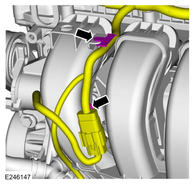
Detach the wiring harness retainer.
-
Detach the wiring harness connector retainer and position the wiring harness aside.
-
Remove the air cleaner outlet pipe.
Refer to: Air Cleaner Outlet Pipe (303-12C Intake Air Distribution and
Filtering - 2.0L Duratec-HE (129kW/175PS), Removal and Installation).
-
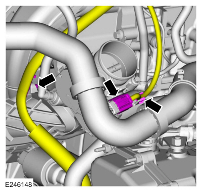
Disconnect the throttle body electrical connector and detach the wire harness retainers.
-
Disconnect the EVAP canister purge valve tube quick release coupling.
Refer to: Quick Release Coupling (310-00 Fuel System -
General Information - 2.0L Duratec-HE (129kW/175PS), 2.0L Duratec-HE
(125kW/170PS) – MI4, 2.0L Duratec-HE Flex Fuel (129kW/175PS))
.
-
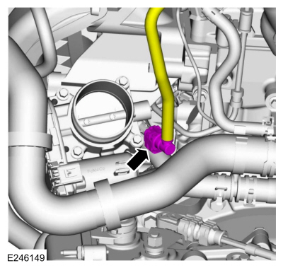
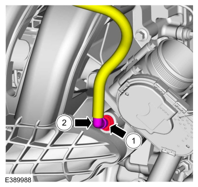
-
Depress the red quick connect locking ring.
-
Pull the vacuum tube out of the quick connect locking ring.
-
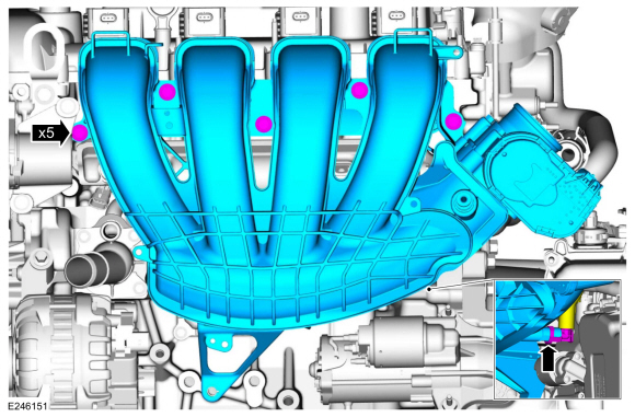
NOTE:
Position back the intake manifold to allow access
to disconnect the crankcase ventilation oil separator tube from the
intake manifold.
-
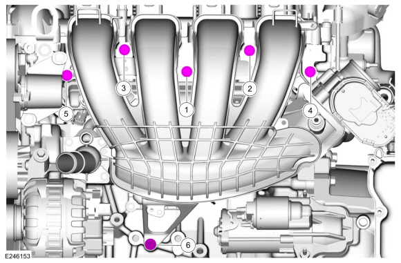
Remove the bolts and the intake manifold.
-
Disconnect the crankcase vent oil separator tube.
-
-
Visually inspect the intake manifold gaskets for
nicks, cuts and abrasions. If these conditions are not present, the
gaskets may be reused.
-
Install new intake manifold gaskets if necessary.
-
Clean and inspect all of the sealing surfaces of the intake manifold.
-
-
If the engine is repaired or replaced because of
upper engine failure, typically including valve or piston damage, check
the intake manifold for metal debris.
-
If metal debris is found, install a new intake manifold.
Installation
-
NOTE:
Make sure the KS wiring connectors are properly routed and not trapped
behind the intake manifold while installing the intake manifold.
-
Connect the crankcase vent oil separator tube.
-
Install the intake manifold and the bolts finger tight.
-
Install the bottom intake manifold mounting bolt finger tight.
-
Tighten the intake manifold bolts in sequence shown.
Torque:
177 lb.in (20 Nm)
-
-
Depress the red quick connect locking ring.
-
Install the vacuum tube in the quick connect locking ring.
-
Connect the EVAP canister purge valve tube quick release coupling.
Refer to: Quick Release Coupling (310-00 Fuel System -
General Information - 2.0L Duratec-HE (129kW/175PS), 2.0L Duratec-HE
(125kW/170PS) – MI4, 2.0L Duratec-HE Flex Fuel (129kW/175PS))
.
-
Connect the throttle body electrical connector and attach the wire harness retainers.
-
Install the air cleaner outlet pipe.
Refer to: Air Cleaner Outlet Pipe (303-12C Intake Air Distribution and
Filtering - 2.0L Duratec-HE (129kW/175PS), Removal and Installation).
-
-
Attach the wiring harness connector retainer.
-
Attach the wiring harness retainer.
-
-
Attach the KS wiring harness connector retainers.
-
Attach the wiring harness retainer.
-
If equipped, install the underbody shield and the retainers.
-
NOTE:
Lubricating the grommets with silicone grease will
aid in the installation of the engine appearance cover, and any future
removal and installation of the cover.
-
Lubricate each grommet with silicone grease.
Material: Motorcraft® Silicone Brake Caliper Grease and Dielectric Compound
/ XG-3-A
(ESA-M1C200-A)
(ESE-M1C171-A)
-
Position the engine appearance cover onto engine with the grommets aligned with the studs.
-
Press down on the engine appearance cover at each grommet location to attach the grommets onto the studs.
-
Connect the battery ground.
Refer to: Battery Disconnect and Connect (414-01 Battery, Mounting and Cables, General Procedures).
Special Tool(s) /
General Equipment
303-103
(T74P-6375-A)
Holding Tool, FlywheelT74P-77000-ATKIT-2009TC-F
Removal
Remove the automatic transmission...
Special Tool(s) /
General Equipment
Oil Drain Equipment
Materials
Name
Specification
Motorcraft® Threadlock and SealerTA-25-B
-
Motorcraft® Silicone Gasket and SealantTA-30
WSE-M4G323-A4
Removal
LHD 4WD/LHD FWD
..
Other information:
TCC Hydraulic Circuits
1
Inspect the pump to transmission case hydraulic passages and seals.
2
Inspect the transmission case to main control hydraulic passages.
3
Inspect the main control hydraulic passages.
Torque Converter Clutch (TCC) and Lubrication Circuits TCC Released
..
Overview
The
rear parking aid camera system visually aids the driver while reversing
or reverse parking the vehicle. When reverse gear is selected, the rear
parking aid camera image is displayed on FDIM
. The camera system has features that provide fixed and active
guideline overlays on the video image to assist the driver in aligning
the vehicle, a manual zoom and a visual park aid ..


 Removal and Installation - Flexplate
 Removal and Installation - Oil Pan