Ford Ecosport: Rear End Sheet Metal Repairs / Removal and Installation - Inner Quarter Panel and Wheelhouse
Special Tool(s) /
General Equipment
| Resistance Spotwelding Equipment |
| 8 mm Drill Bit |
| MIG/MAG Welding Equipment |
| Spot Weld Drill Bit |
| Locking Pliers |
Materials
| Name |
Specification |
Seam Sealer
TA-2-B, 3M™ 08308, LORD Fusor® 803DTM |
-
|
Removal
NOTE:
The inner quarter panel is constructed of mild steel and
High-Strength Low Alloy (HSLA) steel. The following is intended as a
guideline for repair. Adjust to meet repair needs.
NOTE:
LH side shown, RH side similar.
-
Depower the SRS
Refer to: Supplemental Restraint System (SRS) Depowering (501-20B Supplemental Restraint System, General Procedures).
-
If Required:
Dimensionally restore the vehicle to pre-damage condition.
Refer to: Body and Frame (501-26 Body Repairs - Vehicle Specific Information and Tolerance Checks, Description and Operation).
-
Remove the following items:
-
Remove the quarter panel.
Refer to: Quarter Panel LH (501-30 Rear End Sheet Metal Repairs, Removal and Installation).
-
Remove the rear seat belt retractor.
Refer to: Rear Seatbelt Retractor (501-20A Seatbelt Systems, Removal and Installation).
-
Reposition the carpeting and wiring harness away from the working area.
-
Remove the welds.
Use the General Equipment: Spot Weld Drill Bit
-
Remove the gusset.
-
Remove the welds.
Use the General Equipment: Spot Weld Drill Bit
-
Remove the corner panel.
-
Remove the welds.
Use the General Equipment: Spot Weld Drill Bit
-
Remove the welds.
Use the General Equipment: Spot Weld Drill Bit
-
Remove the welds at the reinforcement joint.
Use the General Equipment: Spot Weld Drill Bit
-
Remove the welds at the interior reinforcement joint.
Use the General Equipment: Spot Weld Drill Bit
-
Remove the welds at the wheelhouse to floor joint.
Use the General Equipment: Spot Weld Drill Bit
-
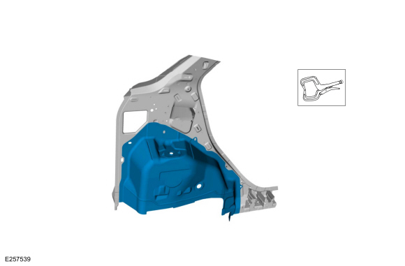
Remove the inner quarter panel and wheelhouse assembly.
Installation
NOTE:
LH side shown, RH side similar.
-
Refer to: Joining Techniques (501-25 Body Repairs - General Information, General Procedures).
-
NOTE:
Sealer or adhesive must not be applied in welding
zones. Areas which were bonded or sealed needs to be thoroughly sealed
afterwards.
-
Drill holes for plug welding.
Use the General Equipment: 8 mm Drill Bit
-
Install the wheelhouse panel to the inner quarter panel and clamp in position.
Use the General Equipment: Locking Pliers
-
Weld the wheelhouse panel.
Use the General Equipment: Resistance Spotwelding Equipment
Use the General Equipment: MIG/MAG Welding Equipment
-
Install the inner quarter panel assembly and clamp in position.
Use the General Equipment: Locking Pliers
-
Weld the flange.
Use the General Equipment: Resistance Spotwelding Equipment
Use the General Equipment: MIG/MAG Welding Equipment
-
Weld the reinforcement joint.
Use the General Equipment: Resistance Spotwelding Equipment
Use the General Equipment: MIG/MAG Welding Equipment
-
Weld the interior reinforcement joint.
Use the General Equipment: MIG/MAG Welding Equipment
-
Install the Welds.
Use the General Equipment: MIG/MAG Welding Equipment
Use the General Equipment: Resistance Spotwelding Equipment
-
Install the Welds.
Use the General Equipment: MIG/MAG Welding Equipment
-
Install, properly position and clamp the corner penal.
Use the General Equipment: Locking Pliers
-
Install the Welds.
Use the General Equipment: MIG/MAG Welding Equipment
-
Install the gusset and clamp in position.
Use the General Equipment: Locking Pliers
-
Weld the gusset.
Use the General Equipment: Resistance Spotwelding Equipment
-
Metal finish as required using typical metal finishing techniques.
-
Sealing work: All areas must be sealed to production level.
Material: Seam Sealer
/ TA-2-B, 3M™ 08308, LORD Fusor® 803DTM
-
Refinish the repair using a Ford approved paint system.
-
Restore corrosion protection.
Refer to: Corrosion Prevention (501-25 Body Repairs - General Information, General Procedures).
-
Reposition the carpeting and the wiring harness to original location.
-
Install the following items:
-
Install the quarter panel.
Refer to: Quarter Panel LH (501-30 Rear End Sheet Metal Repairs, Removal and Installation).
-
Install the rear seat belt retractor.
Refer to: Rear Seatbelt Retractor (501-20A Seatbelt Systems, Removal and Installation).
-
Repower the SRS.
Refer to: Supplemental Restraint System (SRS) Repowering (501-20B Supplemental Restraint System, General Procedures).
Special Tool(s) /
General Equipment
Spherical Cutter
Air Body Saw
MIG/MAG Welding Equipment
Locking Pliers
Materials
Name
Specification
Seam SealerTA-2-B, 3M™ 08308, LORD Fusor® 803DTM
-
Removal
NOTE:
LH side shown, RH side similar...
Special Tool(s) /
General Equipment
Resistance Spotwelding Equipment
Spot Weld Drill Bit
Locking Pliers
Materials
Name
Specification
Seam SealerTA-2-B, 3M™ 08308, LORD Fusor® 803DTM
-
Removal
Restore the vehicle to pre-accident dimensions, if required...
Other information:
DTC Chart: BCM
Diagnostics in this manual assume a certain skill level and knowledge of Ford-specific diagnostic practices. REFER to: Diagnostic Methods (100-00 General Information, Description and Operation).
DTC
Description
Action
B10C6:01
Exterior Trunk Antenna: General Electrical Failure..
Removal
WARNING:
The following procedure prescribes critical repair steps
required for correct restraint system operation during a crash. Follow
all notes and steps carefully. Failure to follow step instructions may
result in incorrect operation of the restraint system and increases the
risk of serious personal injury or death in a crash.
NOTE:
Removal steps in this..


 Removal and Installation - Rear Wheelhouse Outer
 Removal and Installation - Back Panel and Reinforcement