Ford Ecosport: Rear End Sheet Metal Repairs / Removal and Installation - Back Panel and Reinforcement
Ford Ecosport 2014-2025 Service and Repair Manual / Body and Paint / Rear End Sheet Metal Repairs / Removal and Installation - Back Panel and Reinforcement
Special Tool(s) / General Equipment
| Resistance Spotwelding Equipment | |
| Spot Weld Drill Bit | |
| Locking Pliers |
Materials
| Name | Specification |
|---|---|
| Seam Sealer TA-2-B, 3M™ 08308, LORD Fusor® 803DTM |
- |
Removal
-
Restore the vehicle to pre-accident dimensions, if required.
Refer to: Body and Frame (501-26 Body Repairs - Vehicle Specific Information and Tolerance Checks, Description and Operation).
-
Remove the following items:
-
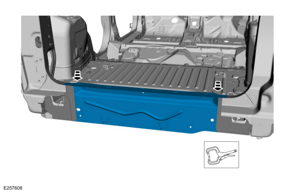
Remove the back panel.
Refer to: Back Panel (501-30 Rear End Sheet Metal Repairs, Removal and Installation).
-
Remove the back panel.
-
Reposition the carpeting and the wiring harness away from the working area.
-
Remove the welds.
Use the General Equipment: Spot Weld Drill Bit
 |
-
NOTE: Use care to avoid damaging adjacent flanges.
Remove the panel.
 |
Installation
NOTE: Sealer or adhesive must not be applied in welding zones. Areas which were bonded or sealed need to be thoroughly sealed afterwards.
-
Refer to: Joining Techniques (501-25 Body Repairs - General Information, General Procedures).
-
Install the panel and position in place.
Use the General Equipment: Locking Pliers
 |
-
Resistance spot weld the panel.
Use the General Equipment: Resistance Spotwelding Equipment
 |
-
Metal finish the welds using typical metal finishing techniques.
-
Sealing work: All areas must be sealed to production level.
Material: Seam Sealer / TA-2-B, 3M™ 08308, LORD Fusor® 803DTM
-
Refinish using a Ford approved paint system.
-
Restore corrosion protection.
Refer to: Corrosion Prevention (501-25 Body Repairs - General Information, General Procedures).
-
Install the following items:
-
Install the back panel.
Refer to: Back Panel (501-30 Rear End Sheet Metal Repairs, Removal and Installation).
-
Install the back panel.
-
Reposition the carpeting and wiring harness.

 Removal and Installation - Front Floor Panel
Special Tool(s) /
General Equipment
Scraper for Straight Edges
Hot Air Gun
8 mm Drill Bit
MIG/MAG Welding Equipment
Spot Weld Drill Bit
Locking Pliers
Materials
Name
Specification
Seam SealerTA-2-B, 3M™ 08308, LORD Fusor® 803DTM
-
Removal
NOTE:
Roof and body side removed for clarity...
Other information:
Ford Ecosport 2014-2025 Service and Repair Manual: Removal and Installation - Valve Tappets
Removal Remove the camshafts. Refer to: Camshaft (303-01C Engine - 2.0L Duratec-HE (129kW/175PS), Removal and Installation). NOTE: If the camshafts and valve tappets are to be reused, mark the location of the valve tappets to make sure they are assembled in their original positions...
Ford Ecosport 2014-2025 Service and Repair Manual: Diagnosis and Testing - Electronic Engine Controls
Diagnostic Trouble Code (DTC) Chart Diagnostics in this manual assume a certain skill level and knowledge of Ford-specific diagnostic practices. REFER to: Diagnostic Methods (100-00 General Information, Description and Operation). Module DTC Description Action PCM P0604:00 Internal Control Module Random Access Memory (RAM) Error: No Sub Type Information GO to Pinpo..
Categories
- Manuals Home
- 2nd Gen Ford Ecosport Service Manual (2014 - 2025)
- Removal and Installation - Evaporative Emission Canister Purge Valve
- Removal and Installation - Starter Motor
- Diagnosis and Testing - Powertrain Control Module (PCM) Input and Output Controls
- Climate Control System - General Information
- Description and Operation - Jacking and Lifting - Overview
Removal and Installation - Front Brake Flexible Hose
Removal
Remove the wheel and tire.Refer to: Wheel and Tire (204-04A Wheels and Tires, Removal and Installation).
Remove the brake flexible hose bracket bolt.
Disconnect the brake tube fitting and remove the brake hose clip.
Loosen the brake hose fitting and remove the brake flexible hose.
Copyright © 2025 www.foecosport2.com