Ford Ecosport: Rear Drive Halfshafts / Removal and Installation - Inner Constant Velocity (CV) Joint Boot
Ford Ecosport 2014-2024 Service and Repair Manual / Driveline / Rear Drive Halfshafts / Removal and Installation - Inner Constant Velocity (CV) Joint Boot
Special Tool(s) / General Equipment
 |
308-046-01 Adapter for 308-046 |
| Flat Headed Screw Driver | |
| Boot Clamp Pliers | |
| Puller | |
| Wooden Block | |
| Copper Hammer | |
| Bearing Separator | |
| Vise | |
| Vise Jaw Protectors | |
Materials
| Name | Specification |
|---|---|
| Grease | WSS-M1C272-A |
Removal
NOTE: Removal steps in this procedure may contain installation details.
-
Remove the rear halfshaft.
Refer to: Rear Halfshaft (205-05 Rear Drive Halfshafts, Removal and Installation).
-
-
Remove and discard the CV joint boot clamps.
Use the General Equipment: Vise
Use the General Equipment: Vise Jaw Protectors
-
Position the CV joint boot back and remove the CV joint tripod housing.
-
Remove and discard the CV joint boot clamps.
 |
-
NOTE: Make sure that the component is clean, free of foreign material and lubricant.
-
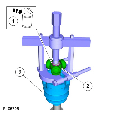
Remove and discard the CV joint tripod circlip.
Use the General Equipment: Puller
Use the General Equipment: Bearing Separator
Use the General Equipment: Vise
Use the General Equipment: Vise Jaw Protectors
-
Remove the CV joint tripod.
-
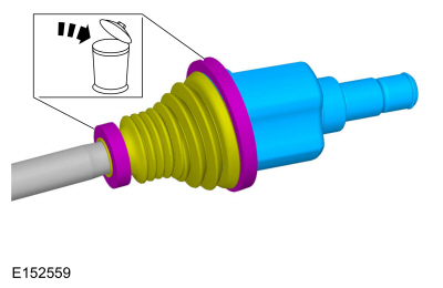
Remove the inner CV joint boot.
-
Remove and discard the CV joint tripod circlip.
 |
Installation
NOTE: Make sure that the component is clean, free of foreign material and lubricant.
-
-
NOTE: Make sure that a new component is installed.
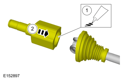
Insert the new small CV joint boot clamp.
Use the General Equipment: Vise
Use the General Equipment: Vise Jaw Protectors
-
Install the inner CV joint boot.
-
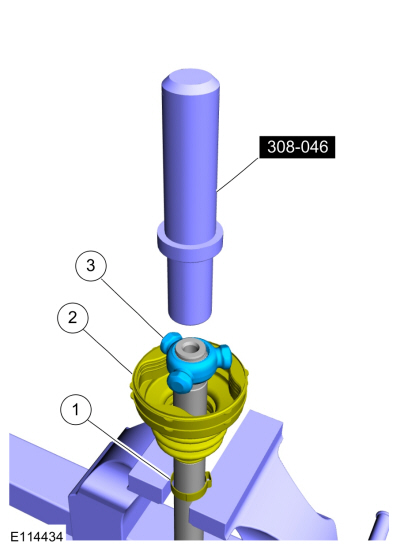
Using the special tool, install the CV joint tripod.
Use Special Service Tool: 308-046-01 Adapter for 308-046.
-
 |
-
-
Install the new CV joint tripod circlip.
Use the General Equipment: Vise
Use the General Equipment: Vise Jaw Protectors
-
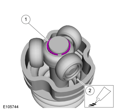
Apply the grease sachet evenly in the CV joint case.
Material: Grease (WSS-M1C272-A)
-
Install the new CV joint tripod circlip.
 |
-
-
Apply the supplied grease sachet from the halfshaft boot kit evenly to both halves of the CV joint.
Material: Grease (WSS-M1C272-A)
-
Slide the CV tripod in the tripod housing.
Use the General Equipment: Wooden Block
Use the General Equipment: Copper Hammer
-
Apply the supplied grease sachet from the halfshaft boot kit evenly to both halves of the CV joint.
 |
-
-
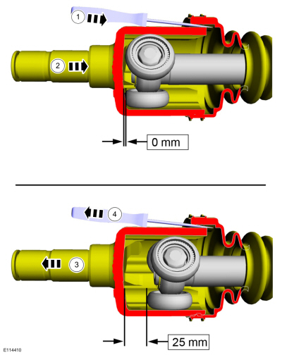
Insert the intermediate shaft into the CV joint boot. Use a flat blade screw driver to release trapped air.
Use the General Equipment: Flat Headed Screw Driver
-
Completely slide the intermediate shaft into the CV joint tripod housing until it bottoms out.
-
Slide the intermediate shaft out 25mm (1 inch).
-
Remove the flat blade screw driver.
Use the General Equipment: Flat Headed Screw Driver
-
Insert the intermediate shaft into the CV joint boot. Use a flat blade screw driver to release trapped air.
 |
-
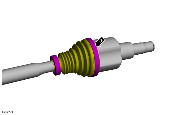
NOTE: Make sure that new components are installed.
NOTE: Do not move the CV joint housing. Make sure that the CV joint boot is installed with the boot in the CV groove.
-
Using the special tool, position back the CV boot and install the new large halfshaft boot clamp.
Use the General Equipment: Boot Clamp Pliers
-
Using the special tool, position back the CV boot and install the new large halfshaft boot clamp.
 |
-
Install the rear halfshaft.
Refer to: Rear Halfshaft (205-05 Rear Drive Halfshafts, Removal and Installation).
 Removal and Installation - Rear Halfshaft
Special Tool(s) /
General Equipment
Tire Lever
Materials
Name
Specification
Motorcraft® SAE 80W-90 Premium Rear Axle LubricantXY-80W90-QL
WSP-M2C197-A
Removal
NOTICE:
Never pick up or hold the halfshaft by only the inner or outer CV joint...
 Removal and Installation - Outer Constant Velocity (CV) Joint Boot
Special Tool(s) /
General Equipment
204-169Clamping Tool, Boot Retaining Clamp
Materials
Name
Specification
Grease
WSS-M1C272-A
Removal
NOTE:
Removal steps in this procedure may contain installation details...
Other information:
Ford Ecosport 2014-2024 Service and Repair Manual: Removal and Installation - Wheel Knuckle - Vehicles With: Rear Disc Brakes
Special Tool(s) / General Equipment 204-161 (T97P-1175-A) Installer, HalfshaftTKIT-1997-LM2TKIT-1997-F/FM2TKIT-1997-FLM2 205-D070 (D93P-1175-B) Remover, Front Wheel Hub Tie Rod End Remover Removal NOTICE: Suspension fasteners are critical parts that affect the performance of vital components and systems...
Ford Ecosport 2014-2024 Service and Repair Manual: Diagnosis and Testing - Pinpoint Test - DTC: P, Vehicles With: Rear Seat Side Airbag
B00C5:11, B00C5:12, B00C5:13, B00C5:1D Refer to Wiring Diagrams Cell 46 for schematic and connector information. Normal Operation and Fault Conditions The RCM continuously monitors the passenger seat position sensor circuits for the following faults: Open circuit Short to voltage Short to ground Current out of range Faulted passenger s..
Categories
- Manuals Home
- 2nd Gen Ford Ecosport Service Manual (2014 - 2024)
- Removal and Installation - Evaporative Emission Canister Purge Valve
- Description and Operation - Jacking and Lifting - Overview
- Anti-Lock Brake System (ABS) and Stability Control
- Removal and Installation - Body Control Module (BCM)
- General Procedures - Transmission Fluid Level Check
Removal and Installation - Wheel Knuckle Bushing
Special Tool(s) / General Equipment
Hydraulic PressRemoval
NOTE: Removal steps in this procedure may contain installation details.
Remove the wheel knuckle.Refer to: Wheel Knuckle - Vehicles With: Rear Drum Brakes (204-02B Rear Suspension - AWD, Removal and Installation).
Remove the rear toe adjustment retainers and remove the wheel knuckle mounting bracket.
Torque:
Stage 1: 177 lb.in (20 Nm)
Stage 2: 76 lb.ft (103 Nm)
Copyright © 2024 www.foecosport2.com