Ford Ecosport: Engine - 2.0L Duratec-HE (129kW/175PS) / Removal and Installation - Cylinder Head
Special Tool(s) /
General Equipment
 |
303-F072
Support Bar, Engine |
| Oil Drain Equipment |
| Trolley Jack |
| Hose Clamp Remover/Installer |
| Wooden Block |
Materials
| Name |
Specification |
Motorcraft® Silicone Brake Caliper Grease and Dielectric Compound
XG-3-A |
ESA-M1C200-A
ESE-M1C171-A
|
Removal
NOTICE:
Do not loosen or remove the crankshaft pulley bolt without
first installing the special tools as instructed in this procedure. The
crankshaft pulley and the crankshaft timing sprocket are not keyed to
the crankshaft. The crankshaft, the crankshaft sprocket and the pulley
are fitted together by friction. For that reason, the crankshaft
sprocket is also unfastened if the pulley bolt is loosened. Before any
repair requiring loosening or removal of the crankshaft pulley bolt, the
crankshaft and camshafts must be locked in place by the special service
tools, otherwise severe engine damage can occur.
NOTICE:
During engine repair procedures, cleanliness is extremely
important. Any foreign material, including any material created while
cleaning gasket surfaces, that enters the oil passages, coolant passages
or the oil pan can cause engine failure.
-
With the vehicle in NEUTRAL, position it on a hoist.
Refer to: Jacking and Lifting - Overview (100-02 Jacking and Lifting, Description and Operation).
-
NOTICE:
Do not pull the engine appearance cover forward or
sideways to remove. Failure to press straight upward on the underside of
the cover at the attachment points may result in damage to the cover or
engine components.
-
Place your hand under the engine appearance cover at
each grommet location and push straight up to release each grommet from
the studs.
-
After all of the grommets have been released from the studs, remove the appearance cover from the engine.
-
Release the fuel system pressure.
Refer to: Fuel System Pressure Release (310-00C Fuel System - General
Information - 2.0L Duratec-HE (129kW/175PS), General Procedures).
-
Disconnect the battery ground.
Refer to: Battery Disconnect and Connect (414-01 Battery, Mounting and Cables, General Procedures).
-
Drain the cooling system.
Refer to: Engine Cooling System Draining, Vacuum Filling and Bleeding
(303-03C Engine Cooling - 2.0L Duratec-HE (129kW/175PS), General
Procedures).
-
Remove the following items:
-
Remove the intake manifold.
Refer to: Intake Manifold (303-01C Engine - 2.0L Duratec-HE (129kW/175PS), Removal and Installation).
-
Remove the camshafts.
Refer to: Camshaft (303-01C Engine - 2.0L Duratec-HE (129kW/175PS), Removal and Installation).
-
Remove the HO2S .
Refer to: Heated Oxygen Sensor (HO2S) (303-14C Electronic Engine
Controls - 2.0L Duratec-HE (129kW/175PS), Removal and Installation).
-
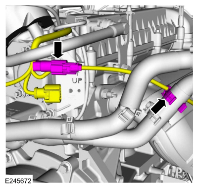
Disconnect the catalyst monitor sensor electrical connector and wire retainer.
-
NOTE:
Typical catalytic converter shown, sensor position may vary by application.
-
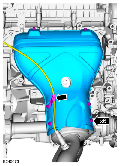
Detach and position the catalyst monitor sensor wiring harness aside.
-
Remove the bolts and the catalytic converter heat shield.
-
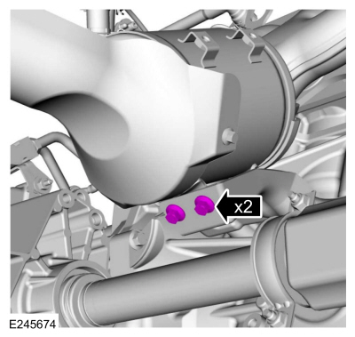
Remove the bolts for the catalytic converter support bracket.
-
-
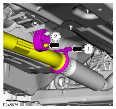
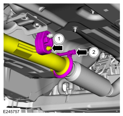
Loosen the catalytic converter-to-muffler and tailpipe nut and separate.
-
Detach the muffler and tailpipe from the hanger.
-
-
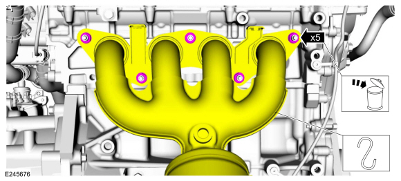
Remove and discard the nuts.
-
Position the catalytic converter aside and support.
-
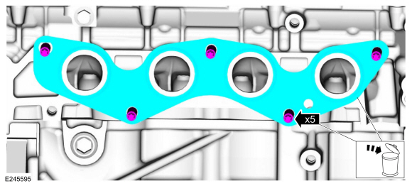
Remove and discard the catalytic converter manifold studs and gasket.
-
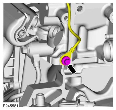
Remove the bolt and the ground wiring harness.
-
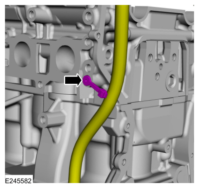
Detach the wiring harness retainer from the back side of the cylinder head.
-
-
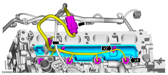
Detach the wiring harness retainers.
-
Disconnect the wiring harness electrical connectors.
-
Remove the fuel rail insulator.
-
-
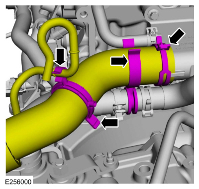
Detach the coolant hose retainers.
-
Release the clamp and position the coolant hose aside.
-
-
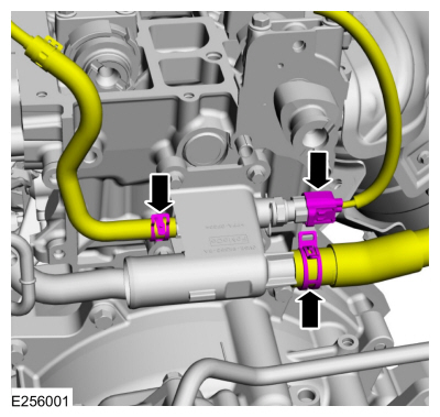
Disconnect the ECT sensor wiring harness electrical connector.
-
Release the clamps and position the coolant hoses aside.
Use the General Equipment: Hose Clamp Remover/Installer
-
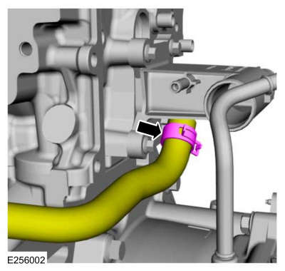
Release the clamp and position the coolant hose aside.
Use the General Equipment: Hose Clamp Remover/Installer
-
NOTE:
If the valve tappets are to be reused, mark the
location of the valve tappets to make sure they are assembled in their
original positions.
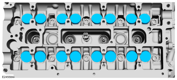
Remove the valve tappets.
-
NOTE:
Do not support the engine on the Air Conditioning (A/C) compressor.
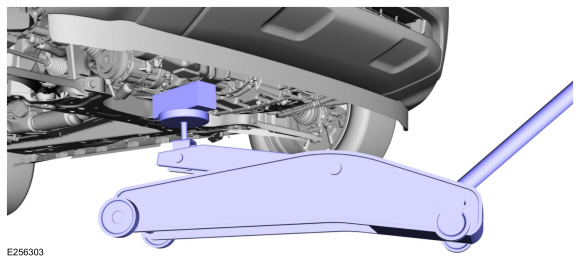
Using a trolley jack and wooden block, support the engine on the oil pan.
Use the General Equipment: Trolley Jack
Use the General Equipment: Wooden Block
-
Remove Special Service Tool: 303-F072
Support Bar, Engine.
-
-
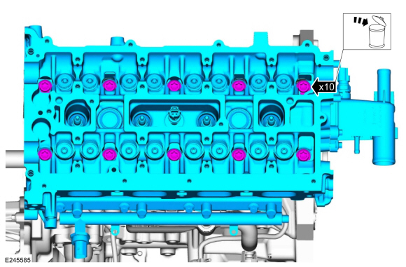
Remove and discard the bolts.
-
Remove the cylinder head.
-
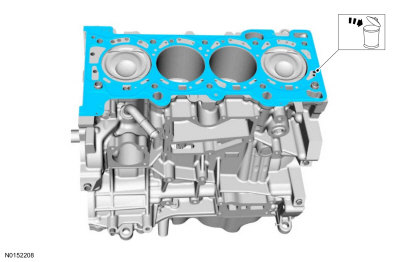
Remove and discard the head gasket.
-
NOTICE:
Do not use metal scrapers, wire brushes, power
abrasive discs or other abrasive means to clean the sealing surfaces.
These tools cause scratches and gouges that make leak paths. Use a
plastic scraping tool to remove all traces of the head gasket.
-
Clean the cylinder head sealing surfaces.
-
Check the cylinder head distortion.
Refer to: Cylinder Head Distortion (303-00 Engine System - General Information, General Procedures).
-
NOTICE:
Do not use metal scrapers, wire brushes, power
abrasive discs or other abrasive means to clean the sealing surfaces.
These tools cause scratches and gouges that make leak paths. Use a
plastic scraping tool to remove all traces of the head gasket.
-
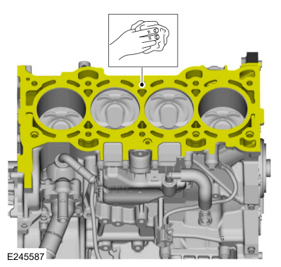
Clean the cylinder block sealing surfaces.
-
Check the cylinder block distortion.
Refer to: Cylinder Block Distortion (303-00 Engine System - General Information, General Procedures).
-
Clean and inspect the catalytic converter manifold.
Refer to: Exhaust Manifold Cleaning and Inspection (303-00 Engine System - General Information, General Procedures).
Installation
-
Install the new cylinder head gasket.
-
NOTE:
The cylinder head bolts are torque-to-yield and must
not be reused. New cylinder head bolts must be installed.
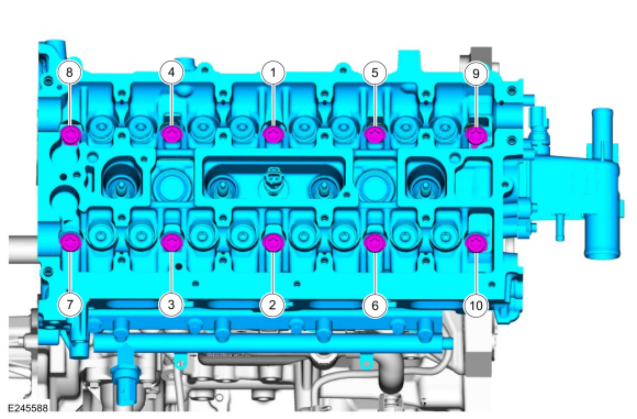
Install the cylinder head and the new bolts and tighten in sequence shown in 5 stages.
Torque:
Stage 1:
62 lb.in (7 Nm)
Stage 2:
133 lb.in (15 Nm)
Stage 3:
26 lb.ft (35 Nm)
Stage 4:
90°
Stage 5:
135°
-
Install Special Service Tool: 303-F072
Support Bar, Engine.
-
Remove the trolley jack and wooden block.
Use the General Equipment: Trolley Jack
Use the General Equipment: Wooden Block
-
Lubricate with clean engine oil and install the valve tappets in their original positions.
-
Position the coolant hose and install.
Use the General Equipment: Hose Clamp Remover/Installer
-
-
Position the coolant hoses and install.
Use the General Equipment: Hose Clamp Remover/Installer
-
Connect the ECT sensor wiring harness electrical connector.
-
-
Position the coolant hose and install.
-
Attach the coolant hose retainers.
-
-
Install the fuel rail insulator.
-
Connect the wiring harness electrical connectors.
-
Attach the wiring harness retainers.
-
Attach the wiring harness retainer to the back side of the cylinder head.
-
Install the ground wiring harness and the bolt.
Torque:
89 lb.in (10 Nm)
-
-
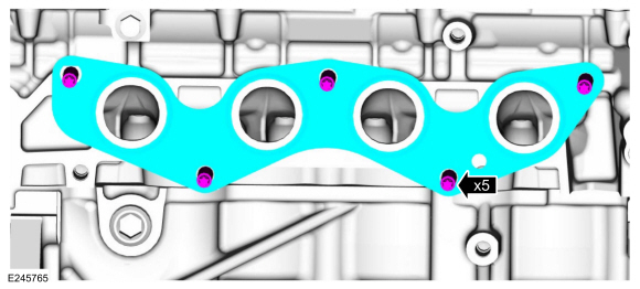
Install the catalytic converter manifold studs.
Torque:
150 lb.in (17 Nm)
-
Install the catalytic converter manifold gasket.
-
-
Remove the support and position the catalytic converter onto the studs.
-
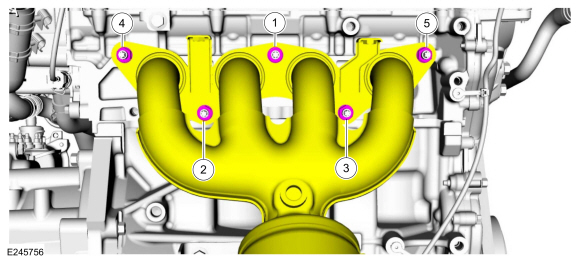
Install the new nuts and tighten in sequence shown.
Torque:
Stage 1:
Tighten:
41 lb.ft (55 Nm)
Stage 2:
Retighten:
41 lb.ft (55 Nm)
-
-
Attach the muffler and tailpipe to the hanger.
-
Connect and tighten the catalytic converter-to-muffler and tailpipe nut.
Torque:
177 lb.in (20 Nm)
-
Install the bolts for the catalytic converter support bracket.
Torque:
18 lb.ft (25 Nm)
-
NOTE:
Typical catalytic converter shown, sensor position may vary by application.
-
Install the catalytic converter heat shield and the bolts.
Torque:
89 lb.in (10 Nm)
-
Attach the catalyst monitor sensor wiring harness.
-
Connect the catalyst monitor sensor electrical connector and wire retainer.
-
-
Remove the drain plug and drain the engine oil.
Use the General Equipment: Oil Drain Equipment
-
Install drain plug.
Torque:
20 lb.ft (27 Nm)
-
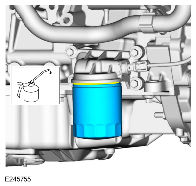
Remove and discard the engine oil filter.
Use the General Equipment: Oil Drain Equipment
-
NOTE:
Lubricate the engine oil filter gasket with clean engine oil prior to installing the oil filter.
Install a new engine oil filter.
Torque:
Stage 1:
71 lb.in (8 Nm)
Stage 2:
180°
-
Remove the following items:
-
Install the HO2S .
Refer to: Heated Oxygen Sensor (HO2S) (303-14C Electronic Engine
Controls - 2.0L Duratec-HE (129kW/175PS), Removal and Installation).
-
Install the camshafts.
Refer to: Camshaft (303-01C Engine - 2.0L Duratec-HE (129kW/175PS), Removal and Installation).
-
Install the intake manifold.
Refer to: Intake Manifold (303-01C Engine - 2.0L Duratec-HE (129kW/175PS), Removal and Installation).
-
Connect the battery ground.
Refer to: Battery Disconnect and Connect (414-01 Battery, Mounting and Cables, General Procedures).
-
NOTE:
Lubricating the grommets with silicone grease will
aid in the installation of the engine appearance cover, and any future
removal and installation of the cover.
-
Lubricate each grommet with silicone grease.
Material: Motorcraft® Silicone Brake Caliper Grease and Dielectric Compound
/ XG-3-A
(ESA-M1C200-A)
(ESE-M1C171-A)
-
Position the engine appearance cover onto engine with the grommets aligned with the studs.
-
Press down on the engine appearance cover at each grommet location to attach the grommets onto the studs.
-
Fill the engine with clean engine oil.
Refer to: Specifications (303-01C Engine - 2.0L Duratec-HE (129kW/175PS), Specifications).
-
Fill and bleed the cooling system.
Refer to: Engine Cooling System Draining, Vacuum Filling and Bleeding
(303-03C Engine Cooling - 2.0L Duratec-HE (129kW/175PS), General
Procedures).
Special Tool(s) /
General Equipment
303-328
(T88P-6701-B1)
Replacer, Rear SealTKIT-1988-FLMTKIT-1988-FTKIT-1988-LM
Oil Drain Equipment
Materials
Name
Specification
Motorcraft® Silicone Gasket and SealantTA-30
WSE-M4G323-A4
Removal
Remove the flexplate...
Special Tool(s) /
General Equipment
303-096
(T74P-6150-A)
Installer, Camshaft Front Oil SealTKIT-2009TC-F
303-1521Alignment Tool, Crankshaft Position SensorTKIT-2010C-FLM
303-1565Alignment Tool, CamshaftTKIT-2010C-FLM
303-1689Holding Tool, Crank Damper
303-409
(T92C-6700-CH)
Remover, Crankshaft SealTKIT-1992-FH/FMH/FLMHTKIT-1993-LMH/M..
Other information:
Special Tool(s) /
General Equipment
205-072Universal Flange Holding Wrench
308-877Installer, Pinion Output SealTKIT-2012A-FLTKIT-2012A-ROW
Puller
Wooden Block
Removal
Remove the transfer case.
Refer to: Transfer Case (308-07B Transfer Case - 6-Speed Automatic Transmission – 6F35, Removal).
Using the sp..
Removal
NOTE:
Removal steps in this procedure may contain installation details.
Remove the front door window regulator.
Refer to: Front Door Window Regulator (501-11 Glass, Frames and Mechanisms, Removal and Installation).
Remove the front door window regulator motor.
Remove the front door window regulator motor bolt.
Torque:
35 lb.i..











 Removal and Installation - Crankshaft Rear Seal
 Removal and Installation - Engine Front Cover
 205-153
(T80T-4000-W)
 205-990