Ford Ecosport: Engine - 2.0L Duratec-HE (129kW/175PS) / Removal and Installation - Engine Front Cover
Special Tool(s) /
General Equipment
 |
303-096
(T74P-6150-A)
Installer, Camshaft Front Oil Seal
TKIT-2009TC-F |
 |
303-1521
Alignment Tool, Crankshaft Position Sensor
TKIT-2010C-FLM |
 |
303-1565
Alignment Tool, Camshaft
TKIT-2010C-FLM |
 |
303-1689
Holding Tool, Crank Damper |
 |
303-409
(T92C-6700-CH)
Remover, Crankshaft Seal
TKIT-1992-FH/FMH/FLMH
TKIT-1993-LMH/MH |
 |
303-507
Timing Peg, Crankshaft TDC
TKIT-2001N-FLM
TKIT-2001N-ROW |
 |
303-F072
Support Bar, Engine |
Materials
| Name |
Specification |
Motorcraft® Silicone Gasket and Sealant
TA-30 |
WSE-M4G323-A4
|
Motorcraft® Silicone Brake Caliper Grease and Dielectric Compound
XG-3-A |
ESA-M1C200-A
ESE-M1C171-A
|
Removal
-
With the vehicle in NEUTRAL, position it on a hoist.
Refer to: Jacking and Lifting - Overview (100-02 Jacking and Lifting, Description and Operation).
-
Remove the following items:
-
Remove the cowl panel.
Refer to: Cowl Panel (501-02 Front End Body Panels, Removal and Installation).
-
Remove the RH headlight assembly.
Refer to: Headlamp Assembly (417-01 Exterior Lighting, Removal and Installation).
-
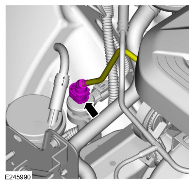
If equipped, disconnect the EVAP tube quick release coupling from the canister purge valve and position aside.
Refer to: Quick Release Coupling (310-00 Fuel System -
General Information - 2.0L Duratec-HE (129kW/175PS), 2.0L Duratec-HE
(125kW/170PS) – MI4, 2.0L Duratec-HE Flex Fuel (129kW/175PS))
.
-
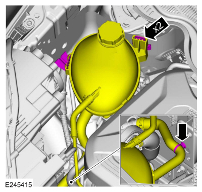
Release the tabs, retainer and position the degas bottle aside.
-
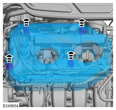
NOTICE:
Do not pull the engine appearance cover forward or
sideways to remove. Failure to press straight upward on the underside of
the cover at the attachment points may result in damage to the cover or
engine components.
-
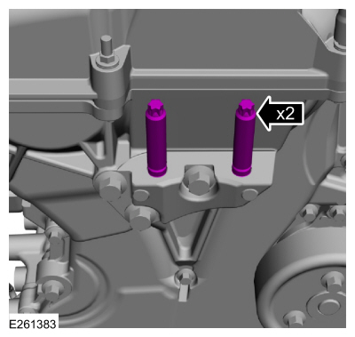
Place your hand under the engine appearance cover at
each grommet location and push straight up to release each grommet from
the studs.
-
After all of the grommets have been released from the studs, remove the appearance cover from the engine.
-
-
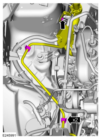
Detach the A/C line retainers.
-
Remove the nut and position the A/C line aside.
-
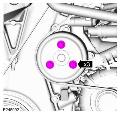
Loosen the coolant pump pulley bolts.
-
Remove the following items:
-
Remove the air cleaner outlet pipe.
Refer to: Air Cleaner Outlet Pipe (303-12C Intake Air Distribution and
Filtering - 2.0L Duratec-HE (129kW/175PS), Removal and Installation).
-
Remove the RH front fender splash shield.
Refer to: Fender Splash Shield (501-02 Front End Body Panels, Removal and Installation).
-
Remove the accessory drive belt.
Refer to: Accessory Drive Belt (303-05C Accessory Drive - 2.0L Duratec-HE (129kW/175PS), Removal and Installation).
-
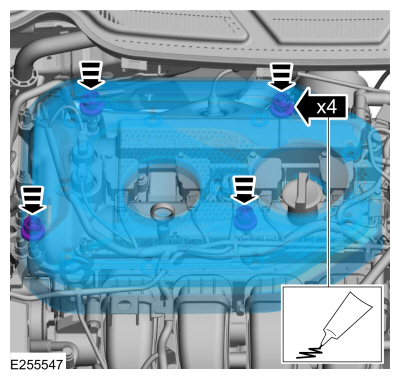
Remove the valve cover.
Refer to: Valve Cover (303-01C Engine - 2.0L Duratec-HE (129kW/175PS), Removal and Installation).
-
-
Disconnect the CKP sensor electrical connector.
-
Remove the bolts and the CKP sensor.
-
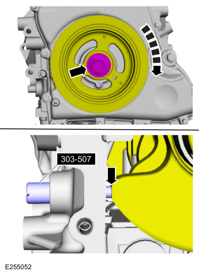
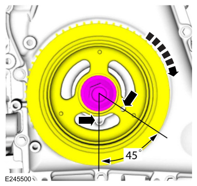
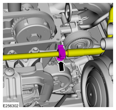
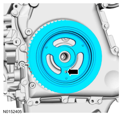
Turn the crankshaft until piston No.1 is 45 degrees before BTDC by
using the guide holes on the engine front cover and the crankshaft
pulley.
-
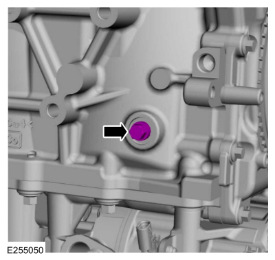
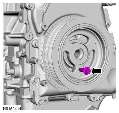
Remove the engine plug bolt.
-
Install Special Service Tool: 303-507
Timing Peg, Crankshaft TDC.
-
NOTE:
The special tool will contact the crankshaft and prevent it from
turning past TDC . However, the crankshaft can still be rotated in the
counterclockwise direction. The crankshaft must remain at the TDC
position during the crankshaft pulley removal and installation.
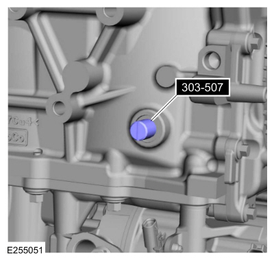
Install the special tool and using the crankshaft pulley
bolt, turn the crankshaft clockwise slowly until contact is made with
the special tool.
Use Special Service Tool: 303-507
Timing Peg, Crankshaft TDC.
 |
|
-
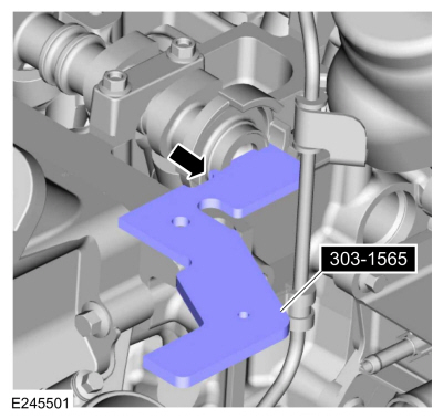
NOTICE:
The special tool is for camshaft alignment only.
Using this tool to prevent engine rotation can result in engine damage.
NOTE:
The camshaft timing slots are offset. If the special
tool cannot be installed, remove the special tools and rotate the
crankshaft three-fourths of a revolution clockwise and repeat the
previous step of this procedure.
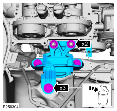
Rotate the special tool so the tool number faces down
and install into the rear of the intake camshaft slot as shown.
Use Special Service Tool: 303-1565
Alignment Tool, Camshaft.
-
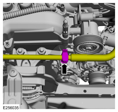
Detach the A/C line retainer and from the engine mount.
-
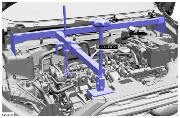
Install Special Service Tool: 303-F072
Support Bar, Engine.
-
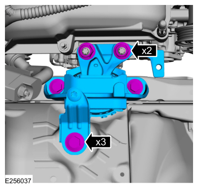
-
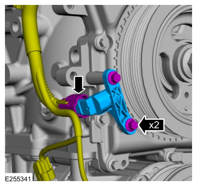
Remove the nuts, bolts and the engine mount.
-
Discard the nuts and bolts.
-
Lower the engine to access the crankshaft pulley.
Use Special Service Tool: 303-F072
Support Bar, Engine.
-
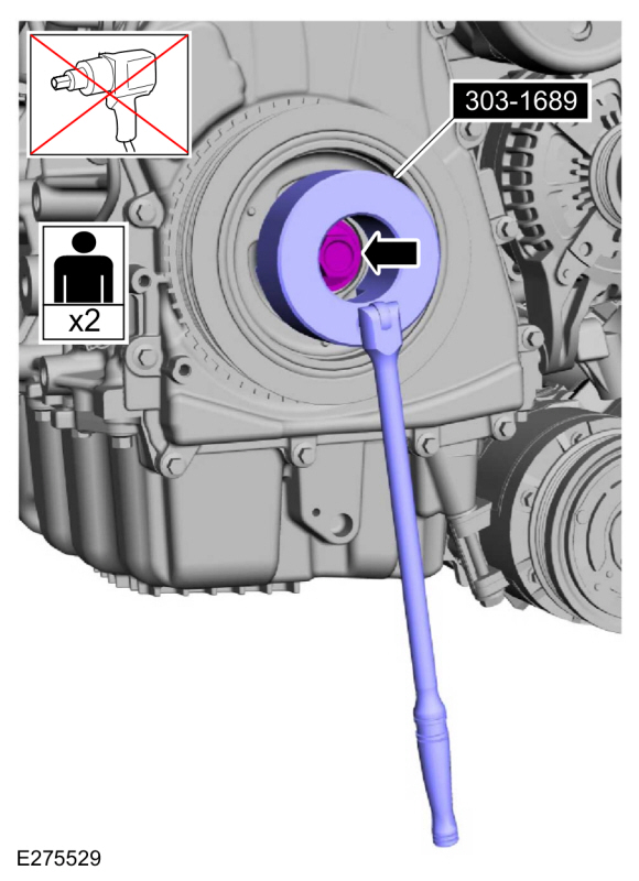
NOTICE:
The crankshaft must remain in the TDC
position during removal of the pulley bolt or damage to the engine can
occur. Therefore, the crankshaft pulley must be held in place with the
Crank Damper Holding Tool and the bolt should be removed using an air
impact wrench (1/2-in drive minimum).
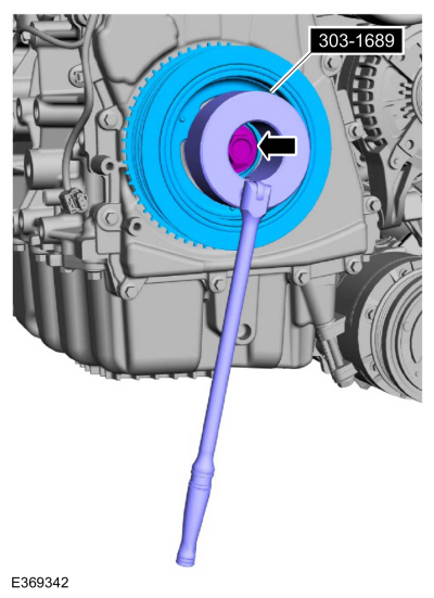
NOTE:
If equipped, the crankshaft sprocket diamond washer may come off with the crankshaft pulley.
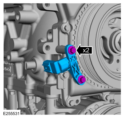
Using the special tool, remove the bolt, washer and the crankshaft pulley.
Use Special Service Tool: 303-1689
Holding Tool, Crank Damper.
-
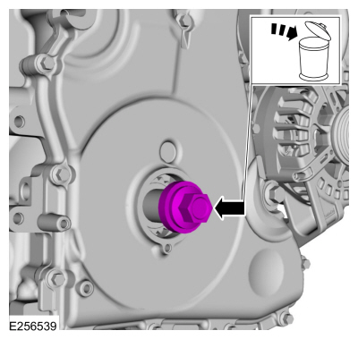
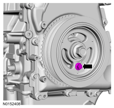
Install the old crankshaft pulley bolt finger tight.
-
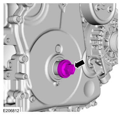
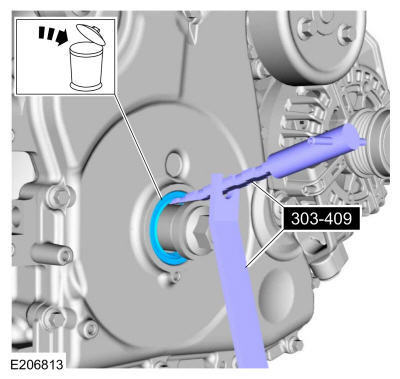
NOTICE:
Use care not to damage the crankshaft or the engine front cover when removing the seal.
Using the special tools, remove the crankshaft front seal.
Use Special Service Tool: 303-409
(T92C-6700-CH)
Remover, Crankshaft Seal.
-
Remove and discard the crankshaft pulley bolt.
-
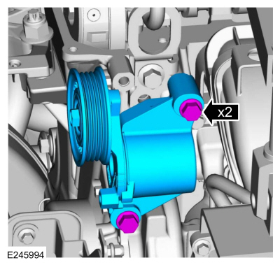
Remove the bolts and the accessory drive belt tensioner.
-
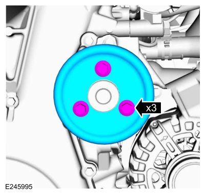
Remove the bolts and the coolant pump pulley.
-
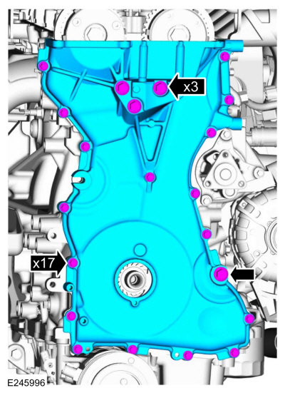
Remove the bolts and the engine front cover.
-
Clean and prepare the RTV sealing surface.
Refer to: RTV Sealing Surface Cleaning and Preparation (303-00 Engine System - General Information, General Procedures).
-
Clean and prepare the RTV sealing surface.
Refer to: RTV Sealing Surface Cleaning and Preparation (303-00 Engine System - General Information, General Procedures).
Installation
-
NOTE:
The engine front cover must be secured within 10
minutes of Silicone Gasket and Sealant application. If the engine front
cover is not secured within 10 minutes, the sealant must be removed and
the sealing area cleaned.
-
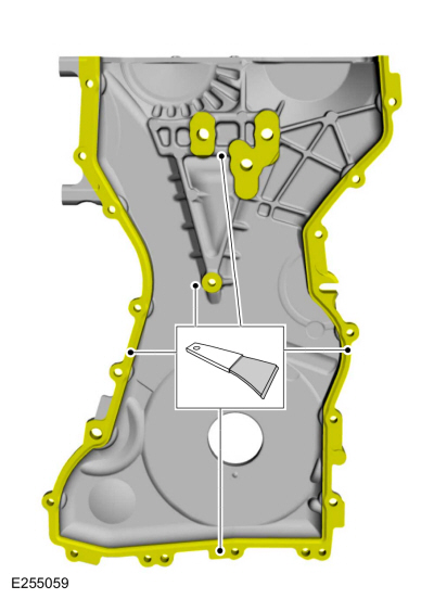
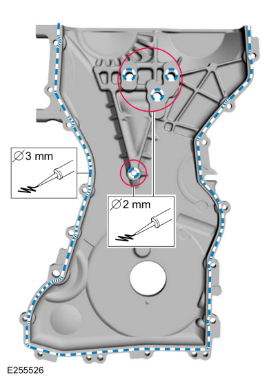
Apply 2 mm beads of silicone sealant around the inner bolt holes.
Material: Motorcraft® Silicone Gasket and Sealant
/ TA-30
(WSE-M4G323-A4)
-
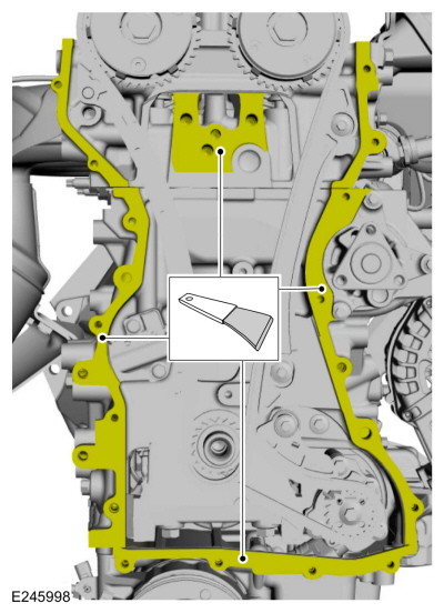
Apply 3 mm bead of silicone sealant on the engine front cover
Material: Motorcraft® Silicone Gasket and Sealant
/ TA-30
(WSE-M4G323-A4)
-
NOTE:
The engine front cover must be secured within 10
minutes of Silicone Gasket and Sealant application. If the engine front
cover is not secured within 10 minutes, the sealant must be removed and
the sealing area cleaned.
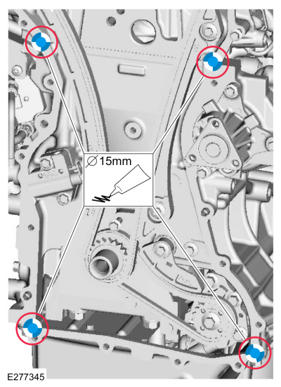
Apply a 15 mm (0.59 in) drop of silicone sealant at the
cylinder head-to-cylinder block and cylinder block-to-oil pan joint
areas.
Material: Motorcraft® Silicone Gasket and Sealant
/ TA-30
(WSE-M4G323-A4)
-
Install the engine front cover and the bolts finger tight.
-
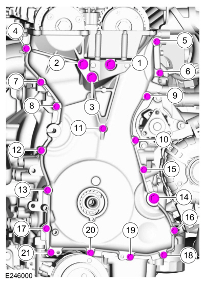
Tighten the engine front cover bolts in sequence shown.
-
Tighten bolts 1 through 3 to
Torque:
35 lb.ft (48 Nm)
-
Tighten bolts 4 through 13 to
Torque:
89 lb.in (10 Nm)
-
Tighten bolt 14 to
Torque:
35 lb.ft (48 Nm)
-
Tighten bolts 15 through 21 to
Torque:
89 lb.in (10 Nm)
-
Install the coolant pump pulley and the bolts finger tight.
-
Install the accessory drive belt tensioner and the bolts.
Torque:
18 lb.ft (25 Nm)
-
NOTE:
Remove the through-bolt from the special tool.
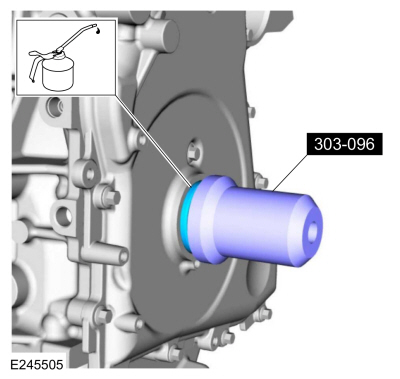
NOTE:
Lubricate the crankshaft front seal with clean engine oil.
Using the special tools, install the crankshaft front seal.
Use Special Service Tool: 303-096
(T74P-6150-A)
Installer, Camshaft Front Oil Seal.
-
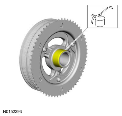
NOTE:
Apply clean engine oil on the seal area before installing.
Lubricate the crankshaft pulley with clean engine oil.
-
Position the crankshaft pulley onto the crankshaft with the access hole at the 6 o'clock position.
-
NOTE:
This step will correctly align the crankshaft pulley to the crankshaft.
Install an M6 bolt.
-
NOTICE:
The crankshaft must remain in the TDC
position during installation of the pulley bolt or damage to the
engine can occur. Therefore, the crankshaft pulley must be held in place
with the Crank Damper Holding Tool and the bolt should be installed
using hand tools only.
Using the special tool, install the new crankshaft bolt and washer and tighten.
Use Special Service Tool: 303-1689
Holding Tool, Crank Damper.
Torque:
Stage 1:
74 lb.ft (100 Nm)
Stage 2:
90°
-
Remove the M6 bolt.
-
Raise the engine to the installed position.
Use Special Service Tool: 303-F072
Support Bar, Engine.
-
Tighten the engine mount studs.
Torque:
93 lb.in (10.5 Nm)
-
-
Install the engine mount and the nuts.
Torque:
59 lb.ft (80 Nm)
-
Install the engine mount bolts.
Torque:
66 lb.ft (90 Nm)
-
Remove Special Service Tool: 303-F072
Support Bar, Engine.
-
Attach the A/C line retainer to the engine mount.
-
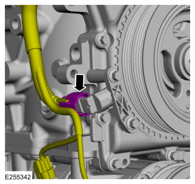
Install the CKP sensor and the bolts finger tight.
-
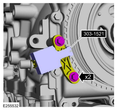
Install the special tool to set the CKP sensor position and tighten the bolts.
Use Special Service Tool: 303-1521
Alignment Tool, Crankshaft Position Sensor.
Torque:
62 lb.in (7 Nm)
-
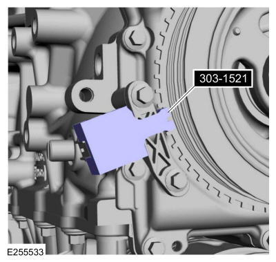
Remove Special Service Tool: 303-1521
Alignment Tool, Crankshaft Position Sensor.
-
Connect the CKP sensor electrical connector.
-
Remove Special Service Tool: 303-507
Timing Peg, Crankshaft TDC.
-
Install the engine plug bolt.
Torque:
177 lb.in (20 Nm)
-
Remove Special Service Tool: 303-1565
Alignment Tool, Camshaft.
-
Install the following items:
-
Install the valve cover.
Refer to: Valve Cover (303-01C Engine - 2.0L Duratec-HE (129kW/175PS), Removal and Installation).
-
Install the accessory drive belt.
Refer to: Accessory Drive Belt (303-05C Accessory Drive - 2.0L Duratec-HE (129kW/175PS), Removal and Installation).
-
Install the RH front fender splash shield.
Refer to: Fender Splash Shield (501-02 Front End Body Panels, Removal and Installation).
-
Install the air cleaner outlet pipe.
Refer to: Air Cleaner Outlet Pipe (303-12C Intake Air Distribution and
Filtering - 2.0L Duratec-HE (129kW/175PS), Removal and Installation).
-
Tighten the coolant pump pulley bolts.
Torque:
177 lb.in (20 Nm)
-
-
Position the A/C line and install the nut.
Torque:
27 lb.in (3 Nm)
-
Attach the A/C line retainers.
-
NOTE:
Lubricating the grommets with silicone grease will
aid in the installation of the engine appearance cover, and any future
removal and installation of the cover.
-
Lubricate each grommet with silicone grease.
Material: Motorcraft® Silicone Brake Caliper Grease and Dielectric Compound
/ XG-3-A
(ESA-M1C200-A)
(ESE-M1C171-A)
-
Position the engine appearance cover onto engine with the grommets aligned with the studs.
-
Press down on the engine appearance cover at each grommet location to attach the grommets onto the studs.
-
Position back the degas bottle and connect the tabs and retainer.
-
If equipped, connect the EVAP tube quick release coupling to the canister purge valve.
Refer to: Quick Release Coupling (310-00 Fuel System -
General Information - 2.0L Duratec-HE (129kW/175PS), 2.0L Duratec-HE
(125kW/170PS) – MI4, 2.0L Duratec-HE Flex Fuel (129kW/175PS))
.
-
Install the following items:
-
Install the RH headlight assembly.
Refer to: Headlamp Assembly (417-01 Exterior Lighting, Removal and Installation).
-
Install the cowl panel.
Refer to: Cowl Panel (501-02 Front End Body Panels, Removal and Installation).
-
Use the Powertrain Control Module (PCM) Misfire Monitor
Profile Correction routine in the diagnostic scan tool.
Special Tool(s) /
General Equipment
Trolley Jack
Wooden Block
Removal
With the vehicle in NEUTRAL, position it on a hoist...
Other information:
Special Tool(s) /
General Equipment
Spring Compressor
Vise
Removal
NOTICE:
Suspension fasteners are critical parts that affect the
performance of vital components and systems. Failure of these fasteners
may result in major service expense...
Item
Description
1
Front stabilizer bar link
2
Stabilizer bar
3
Suspension strut and spring assembly
4
Subframe
5
Lower arm
6
Subframe attachment points
..


 Removal and Installation - Engine Mount