Ford Ecosport: Rear End Sheet Metal Repairs / Removal and Installation - Front Floor Panel
Special Tool(s) / General Equipment
| Scraper for Straight Edges | |
| Hot Air Gun | |
| 8 mm Drill Bit | |
| MIG/MAG Welding Equipment | |
| Spot Weld Drill Bit | |
| Locking Pliers |
Materials
| Name | Specification |
|---|---|
| Seam Sealer TA-2-B, 3M™ 08308, LORD Fusor® 803DTM |
- |
Removal
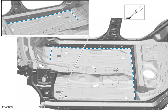
NOTE: Roof and body side removed for clarity.
NOTE: Factory welds may be substituted with resistance or metal inert gas (MIG) plug welds. Resistance welds may not be placed directly over original location. They must be placed adjacent to original location and match factory welds in quantity. Metal inert gas (MIG) plug welds must equal factory welds in both location and quantity.
NOTE: Adequately protect all adjacent areas against cutting, grinding and welding procedures.
-
Depower the SRS .
Refer to: Supplemental Restraint System (SRS) Depowering (501-20B Supplemental Restraint System, General Procedures).
-
If Required:
Dimensionally restore the vehicle to pre-damage condition.
Refer to: Body and Frame (501-26 Body Repairs - Vehicle Specific Information and Tolerance Checks, Description and Operation).
-
On Both Sides:
Remove the front and rear seats.
Refer to: Front Seat (501-10A Front Seats, Removal and Installation).
Refer to: Rear Seat Cushion (501-10B Rear Seats, Removal and Installation).
-
Remove the center console.
Refer to: Floor Console (501-12 Instrument Panel and Console, Removal and Installation).
-
Remove the B-pillar trim panels.
Refer to: B-Pillar Trim Panel (501-05 Interior Trim and Ornamentation, Removal and Installation).
-
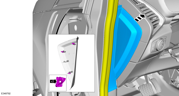
Position aside the weather strip, release the clips and remove the LH instrument panel side trim panel.
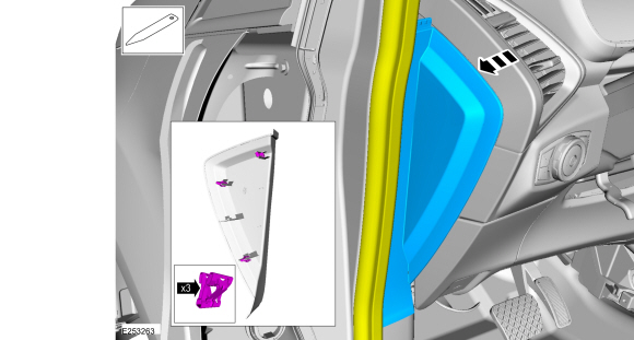 |
-
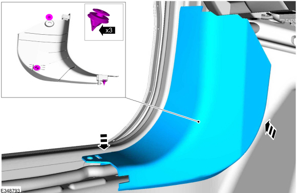
Release the retainers and remove the LH lower cowl trim panel.
 |
-
Remove the parking brake control .
Refer to: Parking Brake Control (206-05 Parking Brake and Actuation, Removal and Installation).
-
Remove the RCM .
Refer to: Restraints Control Module (RCM) (501-20B Supplemental Restraint System, Removal and Installation).
-
Position the carpet and all wiring harnesses away from the working area.
-
Remove the underbody shield(s).
-
Relocate any fuel or brake lines away from the working area.
-
Remove the inner floor panel front reinforcement.
Refer to: Front Floor Panel Upper Front Crossmember (501-30 Rear End Sheet Metal Repairs, Removal and Installation).
-
Remove the inner floor panel rear reinforcement.
Refer to: Front Floor Panel Upper Rear Crossmember (501-30 Rear End Sheet Metal Repairs, Removal and Installation).
-
Remove the seam sealer.
Use the General Equipment: Hot Air Gun
Use the General Equipment: Scraper for Straight Edges
 |
-
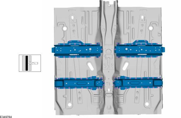
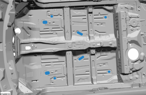
Remove the welds.
Use the General Equipment: Spot Weld Drill Bit
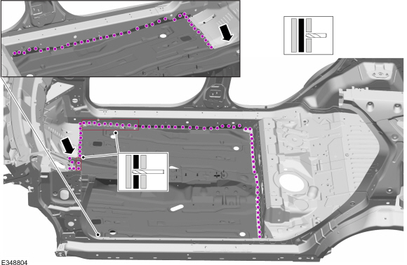 |
-
NOTE: Pay particular attention to the location of adhesives and sealers to aid in installation.
Remove the front floor panel.
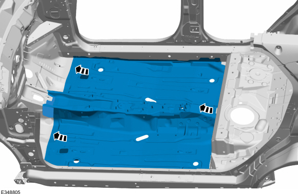 |
Installation
NOTE: Roof and body side removed for clarity.
NOTE: Factory welds may be substituted with resistance or metal inert gas (MIG) plug welds. Resistance welds may not be placed directly over original location. They must be placed adjacent to original location and match factory welds in quantity. Metal inert gas (MIG) plug welds must equal factory welds in both location and quantity.
NOTE: Adequately protect all adjacent areas against cutting, grinding and welding procedures.
-
Remove the crossmember.
Use the General Equipment: Spot Weld Drill Bit
 |
-
Drill plug welds holes in the replacement front floor panel.
Use the General Equipment: 8 mm Drill Bit
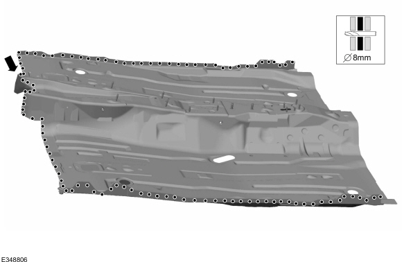 |
-
Install, properly position and clamp the front floor panel.
Use the General Equipment: Locking Pliers
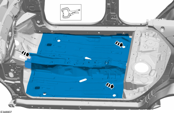 |
-
Install the welds.
Use the General Equipment: MIG/MAG Welding Equipment
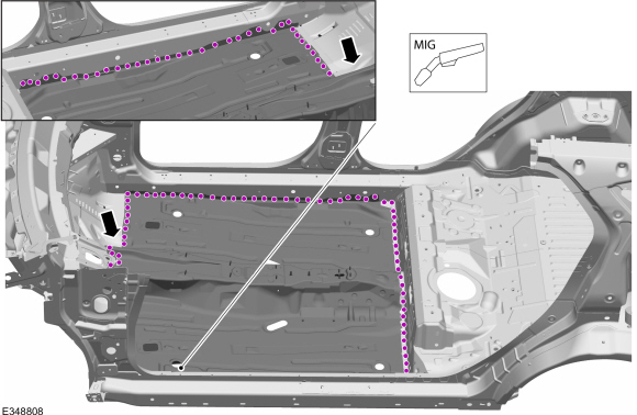 |
-
Dress all welds as required using typical metal finishing techniques.
-
Seam Sealing:
All seams must be sealed to production level.
Material: Seam Sealer / TA-2-B, 3M™ 08308, LORD Fusor® 803DTM
 |
-
Install the inner floor panel rear reinforcement.
Refer to: Front Floor Panel Upper Rear Crossmember (501-30 Rear End Sheet Metal Repairs, Removal and Installation).
-
Install the inner floor panel front reinforcement.
Refer to: Front Floor Panel Upper Front Crossmember (501-30 Rear End Sheet Metal Repairs, Removal and Installation).
-
Install new or transfer the floor panel plugs.
 |
-
Install locally obtained NVH (noise, vibration and harshness) mastic pads.
-
Refinish the entire repair using a Ford approved paint system.
-
Reposition all wiring harnesses and the carpet to original locations.
-
Install the RCM .
Refer to: Restraints Control Module (RCM) (501-20B Supplemental Restraint System, Removal and Installation).
-
Install the parking brake control .
Refer to: Parking Brake Control (206-05 Parking Brake and Actuation, Removal and Installation).
-
Install the center console.
Refer to: Floor Console (501-12 Instrument Panel and Console, Removal and Installation).
-
On Both Sides:
Install the front and rear seats.
Refer to: Front Seat (501-10A Front Seats, Removal and Installation).
Refer to: Rear Seat Cushion (501-10B Rear Seats, Removal and Installation).
-
Install the LH lower cowl trim panel.
 |
-
Install the LH instrument panel side trim panel, Install the weather strip.
 |
-
Install the B-pillar trim panels.
Refer to: B-Pillar Trim Panel (501-05 Interior Trim and Ornamentation, Removal and Installation).
-
Restore corrosion protection.
Refer to: Corrosion Prevention (501-25 Body Repairs - General Information, General Procedures).
-
Reposition any fuel or brake lines to original locations.
-
Install the underbody shield(s).
-
Repower the SRS .
Refer to: Supplemental Restraint System (SRS) Repowering (501-20B Supplemental Restraint System, General Procedures).
 Removal and Installation - Back Panel and Reinforcement
Special Tool(s) /
General Equipment
Resistance Spotwelding Equipment
Spot Weld Drill Bit
Locking Pliers
Materials
Name
Specification
Seam SealerTA-2-B, 3M™ 08308, LORD Fusor® 803DTM
-
Removal
Restore the vehicle to pre-accident dimensions, if required...
 Removal and Installation - Front Floor Panel Bracket and Support
Special Tool(s) /
General Equipment
8 mm Drill Bit
MIG/MAG Welding Equipment
Spot Weld Drill Bit
Locking Pliers
Materials
Name
Specification
Seam SealerTA-2-B, 3M™ 08308, LORD Fusor® 803DTM
-
Removal
NOTE:
Factory welds may be substituted with resistance or metal
inert gas (MIG) plug welds...
Other information:
Ford Ecosport 2014-2025 Service and Repair Manual: General Procedures - Body Panel Sectioning
Special Tool(s) / General Equipment Resistance Spotwelding Equipment Plasma Cutter Air Body Saw MIG/MAG Welding Equipment Spot Weld Drill Bit Materials Name Specification Seam SealerTA-2-B, 3M™ 08308, LORD Fusor® 803DTM - Repair NOTICE: Do not begin removal of the vehicle body side until the replacement pa..
Ford Ecosport 2014-2025 Service and Repair Manual: General Procedures - Headlamp Adjustment
Adjustment NOTE: If the flash video link does not load or is incompatible with your browser, a .wmv version of the video can be accessed at: http://www.fordservicecontent.com/Ford_Content/videos/FusionHeadlampAdj2.wmv Click on the link above to view video. Click here to view a video version of this procedure. All headlamp types NOTE: ..
Categories
- Manuals Home
- 2nd Gen Ford Ecosport Service Manual (2014 - 2025)
- Removal and Installation - Body Control Module (BCM)
- Body and Paint
- Description and Operation - Jacking and Lifting - Overview
- Diagnosis and Testing - Powertrain Control Module (PCM) Input and Output Controls
- Removal and Installation - Evaporative Emission Canister Purge Valve
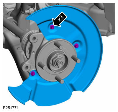
Removal and Installation - Brake Disc Shield
Removal
NOTE: Removal steps in this procedure may contain installation details.
Remove the brake disc.Refer to: Brake Disc (206-03 Front Disc Brake, Removal and Installation).
Remove the bolts and brake disc.
Torque: 80 lb.in (9 Nm)