Ford Ecosport: Rear Drive Axle/Differential / Removal and Installation - Axle Assembly
Removal
NOTE: Removal steps in this procedure may contain installation details.
-
Remove the rear subframe - AWD.
Refer to: Rear Subframe - AWD (502-00 Uni-Body, Subframe and Mounting System, Removal and Installation).
-
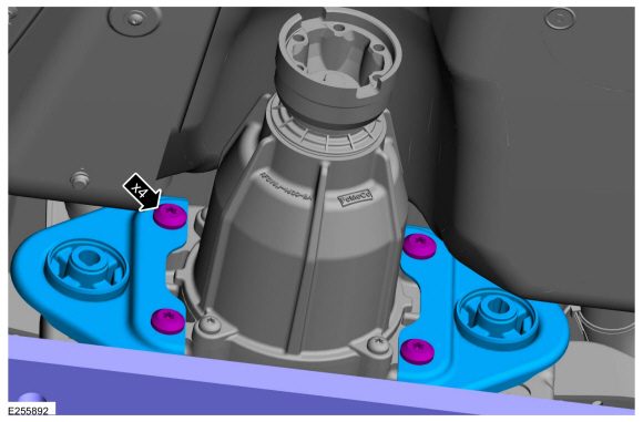
Remove the bolts and the RDU front mounting brackets.
Torque: 66 lb.ft (90 Nm)
 |
-
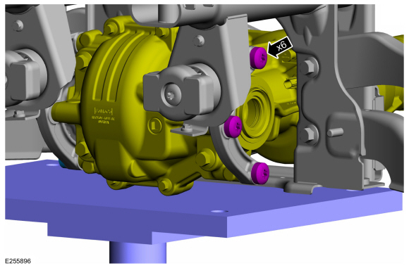
Remove the RDU rear mounting bolts.
Torque: 66 lb.ft (90 Nm)
 |
-
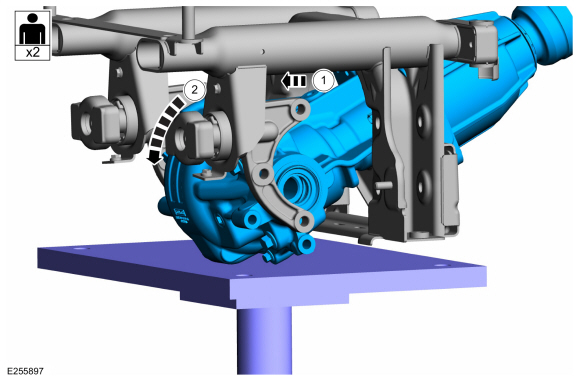
NOTE: This step requires the aid of another technician.
Remove the RDU .
-
Move the RDU backward.
-
Slowly tilt the RDU and down.
-
Move the RDU backward.
 |
Installation
-
NOTICE: If replacing the axle assembly, the 4X4 control module will need to be reconfigured with the new Active Torque Coupling (ATC) bar code information. If the new bar code information does not match the existing 4X4 control module information, driveline damage or driveability concerns can occur.
If installing a new RDU , re-configure the Active Torque Coupling (ATC).
Refer to: Four-Wheel Drive Systems - Overview (308-07A Four-Wheel Drive Systems, Description and Operation).
-
To install, reverse the removal procedure.
-
Fill the differential fluid.
Refer to: Differential Draining and Filling (205-02 Rear Drive Axle/Differential, General Procedures).
 Removal and Installation - Active Torque Coupling Clutch
Special Tool(s) /
General Equipment
205-126
(T78P-4851-A)
Holding Fixture, Drive Pinion Flange
Tire Lever
Materials
Name
Specification
Motorcraft® Silicone Gasket and SealantTA-30
WSE-M4G323-A4
Removal
NOTICE:
When replacing the RDU clutch, the ATC coil and yoke are a matched set and must be replaced also...
 Removal and Installation - Differential Rear Bushing
Special Tool(s) /
General Equipment
204-598-01Remover/Installer, Subframe Bushing Guide
205-271Installer, Pivot Bushing
Transmission Jack
Removal
With the vehicle in NEUTRAL, position it on a hoist...
Other information:
Ford Ecosport 2014-2025 Service and Repair Manual: General Procedures - Engine Cooling System Flushing
Materials Name Specification Motorcraft® Premium Cooling System FlushVC-1 ESR-M14P7-A Flushing WARNING: Always allow the engine to cool before opening the cooling system. Do not unscrew the coolant pressure relief cap when the engine is operating or the cooling system is hot...
Ford Ecosport 2014-2025 Service and Repair Manual: Removal and Installation - Engine Coolant Temperature (ECT) Sensor
Removal NOTE: Removal steps in this procedure may contain installation details. Drain the cooling system. Refer to: Cooling System Draining, Vacuum Filling and Bleeding (303-03J) . Remove the engine appearance cover...
Categories
- Manuals Home
- 2nd Gen Ford Ecosport Service Manual (2014 - 2025)
- Climate Control System - General Information
- Service Information
- Body and Paint
- Removal and Installation - Block Heater
- Description and Operation - Evaporative Emissions - System Operation and Component Description
Description and Operation - Health and Safety Precautions
General Service Warnings
Review carefully the information below before beginning any repair. Following these warnings is a list of specific system warnings that must be reviewed before beginning work on any listed system.
 WARNING:
Wear eye and ear protection when servicing a vehicle.
Failure to follow this instruction may result in serious personal
injury.
WARNING:
Wear eye and ear protection when servicing a vehicle.
Failure to follow this instruction may result in serious personal
injury.