Ford Ecosport: Rear Drive Axle/Differential / Removal and Installation - Active Torque Coupling Clutch
Special Tool(s) / General Equipment
 |
205-126
(T78P-4851-A)
Holding Fixture, Drive Pinion Flange |
| Tire Lever | |
Materials
| Name | Specification |
|---|---|
| Motorcraft® Silicone Gasket and Sealant TA-30 |
WSE-M4G323-A4 |
Removal
NOTICE: When replacing the RDU clutch, the ATC coil and yoke are a matched set and must be replaced also.
NOTICE: When replacing the RDU clutch, the 4X4 control module will need to be reconfigured with the new Active Torque Coupling (ATC) bar code information. If the new bar code information does not match the existing 4X4 control module information, driveline damage or driveability concerns can occur.
NOTE: Removal steps may contain installation instructions.
-
With the vehicle in NEUTRAL, position it on a hoist.
Refer to: Jacking and Lifting - Overview (100-02 Jacking and Lifting, Description and Operation).
-
Remove the driveshaft.
Refer to: Driveshaft (205-01 Driveshaft, Removal and Installation).
-
Disconnect the Active Torque Coupling (ATC) connector.
 |
-
Remove the bolts and the RDU front mounting bracket.
Torque: 66 lb.ft (90 Nm)
 |
-
Remove and discard the RDU coupler housing bolts.
Torque: 30 lb.ft (40 Nm)
 |
-
NOTE: When assembling use a 2 mm bead of silicon sealant.
NOTE: The RDU coupler housing should be dry. The presence of fluid in the housing cavity is most likely from a failed / overheated Active Torque Coupling (ATC). Clean any fluid from the housing before assembly.
Using a pry bar, remove the RDU coupler housing.
Use the General Equipment: Tire Lever
Material: Motorcraft® Silicone Gasket and Sealant / TA-30 (WSE-M4G323-A4)
 |
-
Using the special tool, remove the companion flange bolt, washer and the companion flange. Discard the bolt.
Use Special Service Tool: 205-126 (T78P-4851-A) Holding Fixture, Drive Pinion Flange.
Torque: 40 lb.ft (54 Nm)
 |
-
Index mark the companion flange and stub shaft.
 |
-
Remove the companion flange.
 |
-
Remove the RDU clutch coupler housing from the Intelligent Torque Controlled Coupling (ITCC).
 |
-
Remove and discard the stub shaft bolts. Remove the stub shaft.
Torque: 43 lb.ft (58 Nm)
 |
-
Remove and discard the Active Torque Coupling (ATC) coil snap ring.
 |
-
NOTE: The ATC coil and the ATC coil yoke must be replaced as a matched set.
Remove the Active Torque Coupling (ATC) coil.
 |
-
NOTE: The ATC coil and the ATC coil yoke must be replaced as a matched set.
Remove the bolts and the Active Torque Coupling (ATC) coil yoke. Discard the bolts.
Torque: 89 lb.in (10 Nm)
 |
-
Clean the mating surface of the RDU differential housing.
Refer to: RTV Sealing Surface Cleaning and Preparation (303-00 Engine System - General Information, General Procedures).
 |
-
Clean the mating surface of the RDU clutch coupler housing.
Refer to: RTV Sealing Surface Cleaning and Preparation (303-00 Engine System - General Information, General Procedures).
 |
Installation
-
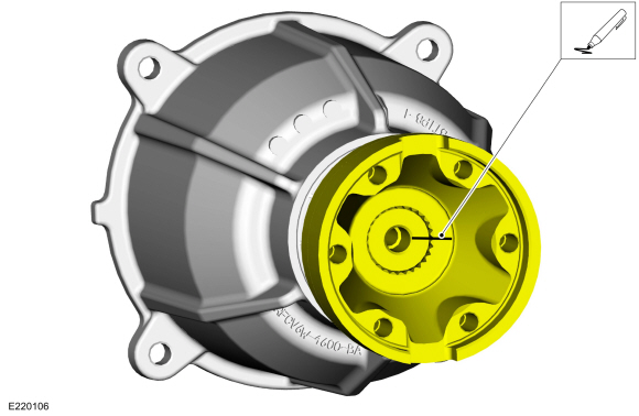
Record the etched 4-digit calibration code from the new RDU clutch coupler.
 |
-
If the new 4-digit calibration code from the RDU clutch
coupler does not match the 4-digit calibration code on the RDU clutch
coupler housing, strike out the existing 4-digit calibration code on the
RDU clutch coupler housing and write the new 4-digit calibration code
with permanent felt tip marker.
 |
-
To install, reverse the removal procedure.
 General Procedures - Differential Fluid Level Check
Check
With the vehicle in NEUTRAL, position it on a hoist.
Refer to: Jacking and Lifting - Overview (100-02 Jacking and Lifting, Description and Operation)...
 Removal and Installation - Axle Assembly
Removal
NOTE:
Removal steps in this procedure may contain installation details.
Remove the rear subframe - AWD.
Refer to: Rear Subframe - AWD (502-00 Uni-Body, Subframe and Mounting System, Removal and Installation)...
Other information:
Ford Ecosport 2014-2025 Service and Repair Manual: Removal and Installation - Tie Rod End
Special Tool(s) / General Equipment 211-001 (TOOL-3290-D) Remover, Tie-Rod End Removal NOTE: Removal steps in this procedure may contain installation details. Remove the wheel and tire. Refer to: Wheel and Tire (204-04A Wheels and Tires, Removal and Installation)...
Ford Ecosport 2014-2025 Service and Repair Manual: Removal and Installation - Cabin Air Filter
Special Tool(s) / General Equipment Interior Trim Remover Removal NOTE: Removal steps in this procedure may contain installation details. Remove the floor console upper trim panel. Disconnect the electrical connectors...
Categories
- Manuals Home
- 2nd Gen Ford Ecosport Service Manual (2014 - 2025)
- Removal and Installation - Front Seat
- Description and Operation - Jacking and Lifting - Overview
- Diagnosis and Testing - Body Control Module (BCM)
- Removal and Installation - Rear Bumper
- General Procedures - Battery Charging
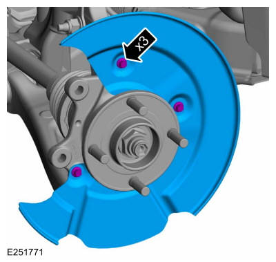
Removal and Installation - Brake Disc Shield
Removal
NOTE: Removal steps in this procedure may contain installation details.
Remove the brake disc.Refer to: Brake Disc (206-03 Front Disc Brake, Removal and Installation).
Remove the bolts and brake disc.
Torque: 80 lb.in (9 Nm)