Ford Ecosport: Side Panel Sheet Metal Repairs / Removal and Installation - A-Pillar Outer Panel Section and Reinforcement
Special Tool(s) / General Equipment
| Resistance Spotwelding Equipment | |
| 8 mm Drill Bit | |
| MIG/MAG Welding Equipment | |
| Spot Weld Drill Bit | |
| Locking Pliers |
Removal
NOTE: Factory welds may be replaced with resistance spot welds or MIG (metal inert gas) plug welds. Resistance spot welds may not be placed directly over original location. They must be placed adjacent to original location and equal factory welds in quantity. MIG (metal inert gas) plug welds must equal factory welds in both location and quantity.
NOTE: Left hand (LH) side shown, right hand(RH) side similar.
NOTE: Adequately protect all adjacent areas against cutting, grinding and welding procedures.
-
Depower the SRS .
Refer to: Supplemental Restraint System (SRS) Depowering (501-20B Supplemental Restraint System, General Procedures).
-
If required:
Dimensionally restore the vehicle to pre-damaged condition.
Refer to: Body and Frame (501-26 Body Repairs - Vehicle Specific Information and Tolerance Checks, Description and Operation).
-
Remove the side panel.
Refer to: Side Panel (501-29 Side Panel Sheet Metal Repairs, Removal and Installation).
-
Remove the cowl panel.
Refer to: Cowl Panel (501-27 Front End Sheet Metal Repairs, Removal and Installation).
-
Remove the B-pillar.
Refer to: B-Pillar and Reinforcement (501-29 Side Panel Sheet Metal Repairs, Removal and Installation).
-
Position the carpeting and the wiring harness away from the working area.
-
Remove the welds.
Use the General Equipment: Spot Weld Drill Bit
 |
-
Remove the welds.
Use the General Equipment: Spot Weld Drill Bit
 |
-
Remove the A-pillar reinforcement.
 |
Installation
NOTE: Factory welds may be replaced with resistance spot welds or MIG (metal inert gas) plug welds. Resistance spot welds may not be placed directly over original location. They must be placed adjacent to original location and equal factory welds in quantity. MIG (metal inert gas) plug welds must equal factory welds in both location and quantity.
NOTE: Left hand (LH) side shown, right hand(RH) side similar.
NOTE: Adequately protect all adjacent areas against cutting, grinding and welding procedures.
-
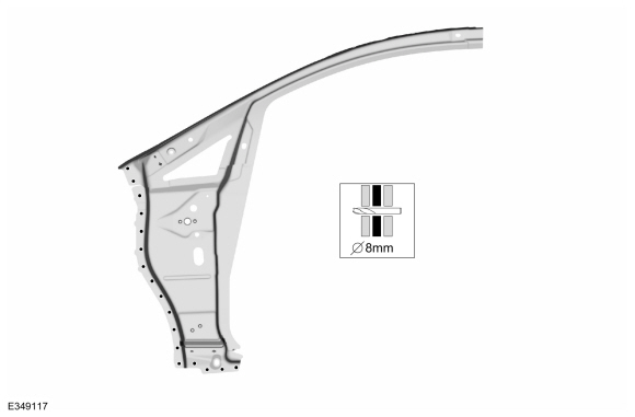
Drill 8 mm holes as indicated.
Use the General Equipment: 8 mm Drill Bit
 |
-
Installl, properly position and clamp the A-pillar reinforcement.
Use the General Equipment: Locking Pliers
 |
-
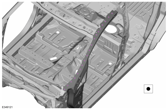
Install the welds.
Use the General Equipment: Resistance Spotwelding Equipment
 |
-
Install the welds.
Use the General Equipment: Resistance Spotwelding Equipment
 |
-
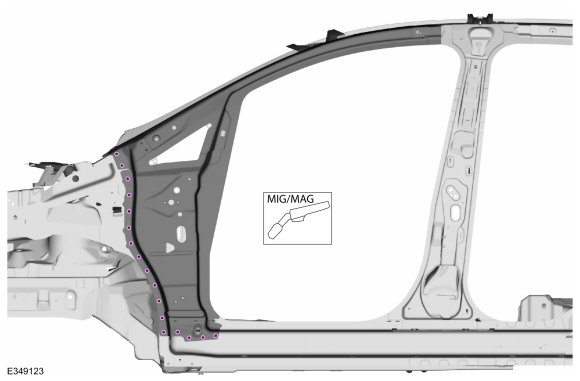
Install the welds.
Use the General Equipment: MIG/MAG Welding Equipment
 |
-
Metal finish all welds as necessary using typical metal finishing techniques.
-
All seams must be sealed to production level.
-
Refinish the entire repair using a Ford approved paint system.
-
Restore corrosion protection.
Refer to: Corrosion Prevention (501-25 Body Repairs - General Information, General Procedures).
-
Reposition the carpeting and the wiring harness to original location.
-
Install the B-pillar.
Refer to: B-Pillar and Reinforcement (501-29 Side Panel Sheet Metal Repairs, Removal and Installation).
-
Install the side panrl.
Refer to: Side Panel (501-29 Side Panel Sheet Metal Repairs, Removal and Installation).
-
Install the cowl panrl.
Refer to: Cowl Panel (501-27 Front End Sheet Metal Repairs, Removal and Installation).
-
Repower the SRS .
Refer to: Supplemental Restraint System (SRS) Repowering (501-20B Supplemental Restraint System, General Procedures).
 Removal and Installation - A-Pillar Outer Panel
Special Tool(s) /
General Equipment
Resistance Spotwelding Equipment
Spherical Cutter
Hot Air Gun
Air Body Saw
8 mm Drill Bit
MIG/MAG Welding Equipment
Spot Weld Drill Bit
Locking Pliers
Removal
Depower the SRS ...
 Removal and Installation - A-Pillar Upper Reinforcement
Special Tool(s) /
General Equipment
Resistance Spotwelding Equipment
Spot Weld Drill Bit
Locking Pliers
Materials
Name
Specification
Seam SealerTA-2-B, 3M™ 08308, LORD Fusor® 803DTM
-
Removal
NOTE:
It is highly recommended the replacement panel be present before making any sectioning cuts on the vehicle...
Other information:
Ford Ecosport 2014-2024 Service and Repair Manual: General Procedures - Adaptive Learning Drive Cycle
Initialization NOTE: The engine and transmission must be at normal operating temperature. Using the scan tool, clear the DTC and Transmission Adaptive Tables. Bring the transmission to normal operating temperature...
Ford Ecosport 2014-2024 Service and Repair Manual: Removal and Installation - Tie Rod End
Special Tool(s) / General Equipment 211-001 (TOOL-3290-D) Remover, Tie-Rod End Removal NOTE: Removal steps in this procedure may contain installation details. Remove the wheel and tire. Refer to: Wheel and Tire (204-04A Wheels and Tires, Removal and Installation)...
Categories
- Manuals Home
- 2nd Gen Ford Ecosport Service Manual (2014 - 2024)
- General Procedures - Transmission Fluid Level Check
- Removal and Installation - Body Control Module (BCM)
- Description and Operation - Evaporative Emissions - System Operation and Component Description
- Service Information
- Removal and Installation - Fuel Filler Door Assembly
Removal and Installation - Front Stabilizer Bar
Special Tool(s) / General Equipment
Tie Rod End Remover Transmission JackRemoval
NOTICE: Suspension fasteners are critical parts that affect the performance of vital components and systems. Failure of these fasteners may result in major service expense. Use the same or equivalent parts if replacement is necessary. Do not use a replacement part of lesser quality or substitute design. Tighten fasteners as specified.
NOTE: Removal steps in this procedure may contain installation details.
NOTICE: Disconnect the b