Ford Ecosport: Side Panel Sheet Metal Repairs / Removal and Installation - A-Pillar Outer Panel
Special Tool(s) /
General Equipment
| Resistance Spotwelding Equipment |
| Spherical Cutter |
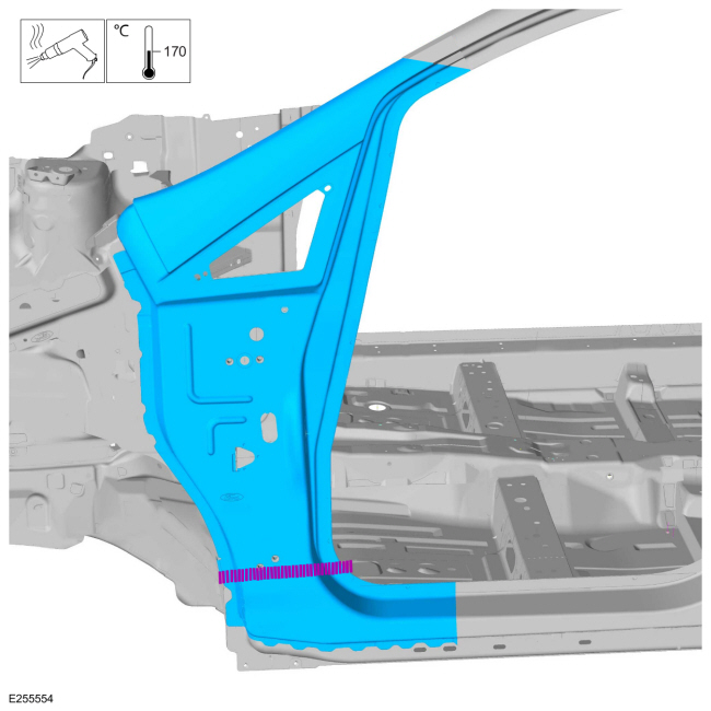
| Hot Air Gun |
| Air Body Saw |
| 8 mm Drill Bit |
| MIG/MAG Welding Equipment |
| Spot Weld Drill Bit |
| Locking Pliers |
Removal
-
Depower the SRS .
Refer to: Supplemental Restraint System (SRS) Depowering (501-20B Supplemental Restraint System, General Procedures).
-
Dimensionally restore the vehicle to pre-accident condition.
Refer to: Body and Frame (501-26 Body Repairs - Vehicle Specific Information and Tolerance Checks, Description and Operation).
-
-
Remove the windshield glass.
-
Remove the sail panel fixed glass.
Refer to: Fixed Glass (501-11 Glass, Frames and Mechanisms, General Procedures).
-
Remove the front door.
Refer to: Front Door (501-03 Body Closures, Removal and Installation).
-
Remove the A-pillar trim panel.
Refer to: A-Pillar Trim Panel (501-05 Interior Trim and Ornamentation, Removal and Installation).
-
Remove the rocker panel moulding.
Refer to: Rocker Panel Moulding (501-08 Exterior Trim and Ornamentation, Removal and Installation).
-
Remove the front seat.
Refer to: Front Seat (501-10A Front Seats, Removal and Installation).
-
Remove the fender apron panel reinforcement.
Refer to: Fender Apron Panel Reinforcement (501-27 Front End Sheet Metal Repairs, Removal and Installation).
-
Reposition the carpeting and the wiring harness away from the working area.
-
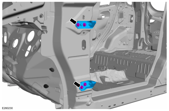
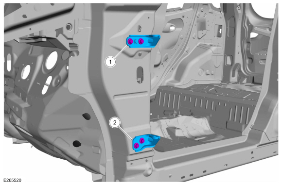
Remove the front door hinges at the A-pillar.
-
-
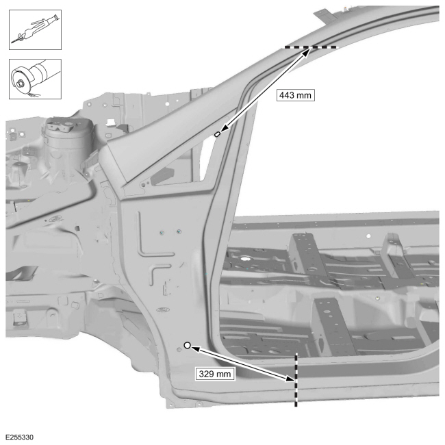
Carefully measure and cut the outer panel.
Use the General Equipment: Air Body Saw
Use the General Equipment: Spherical Cutter
-
-
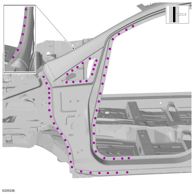
Remove the welds.
Use the General Equipment: Spot Weld Drill Bit
-
Installation
-
NOTE:
Sealer or adhesive must not be applied in welding
zones. Areas which were bonded or sealed needs to be thoroughly sealed
afterwards.
Refer to sealer, underbody protection material and adhesive instructions in the workshop manual.
Refer to: Sealer, Underbody Protection Material and Adhesives (501-25
Body Repairs - General Information, Description and Operation).
-
-
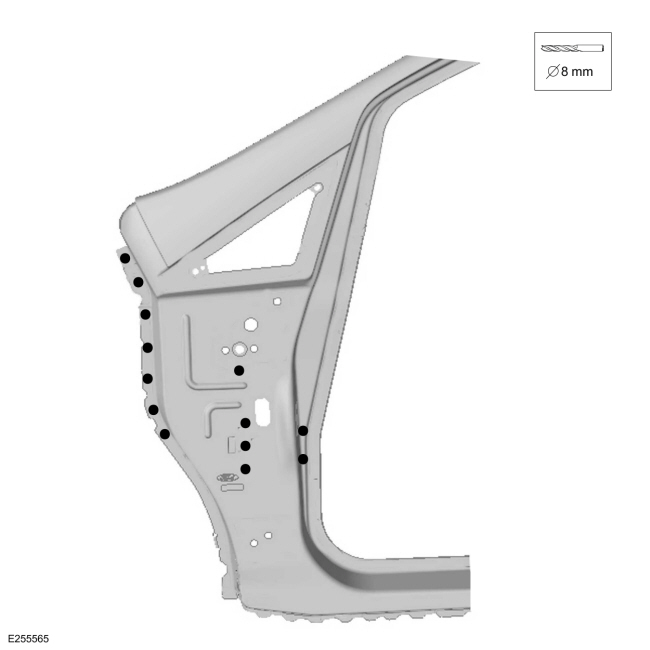
Drill 8 mm holes as indicated.
Use the General Equipment: 8 mm Drill Bit
-
-
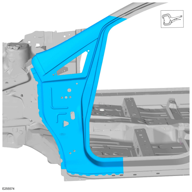
Install properly position and clamp the panel.
Use the General Equipment: Locking Pliers
-
-
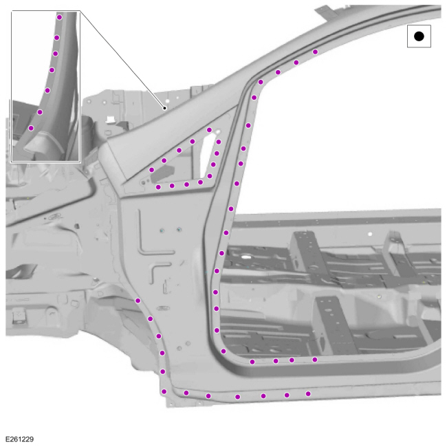
Install the welds.
Use the General Equipment: Resistance Spotwelding Equipment
-
-
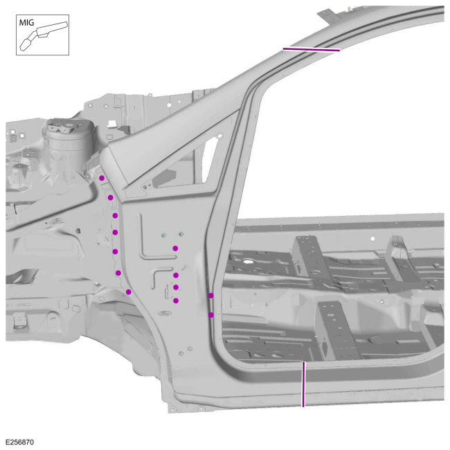
Install MIG plug welds and seam weld sectioning joints.
Use the General Equipment: MIG/MAG Welding Equipment
-
Metal finish as necessary using typical metal finishing techniques and materials.
-
All seams must be sealed to production level.
-
Refinish the repair using a Ford approved paint system.
-
Restore corrosion protection.
Refer to: Corrosion Prevention (501-25 Body Repairs - General Information, General Procedures).
-
-
Install the windshield glass.
-
Install the sail panel fixed glass.
Refer to: Fixed Glass (501-11 Glass, Frames and Mechanisms, General Procedures).
-
Install the front door.
Refer to: Front Door (501-03 Body Closures, Removal and Installation).
Refer to: Front Door Alignment (501-03 Body Closures, General Procedures).
-
Install the A-pillar trim panel.
Refer to: A-Pillar Trim Panel (501-05 Interior Trim and Ornamentation, Removal and Installation).
-
Install the rocker panel moulding.
Refer to: Rocker Panel Moulding (501-08 Exterior Trim and Ornamentation, Removal and Installation).
-
Install the front seat.
Refer to: Front Seat (501-10A Front Seats, Removal and Installation).
-
Install the fender apron panel reinforcement.
Refer to: Fender Apron Panel Reinforcement (501-27 Front End Sheet Metal Repairs, Removal and Installation).
-
Install the front door hinges at the A-pillar.
-
Upper hinge:
Torque:
30 lb.ft (40 Nm)
-
Lower hinge:
Torque:
26 lb.ft (35 Nm)
-
Install and adjust the door.
Refer to: Front Door (501-03 Body Closures, Removal and Installation).
Refer to: Front Door Alignment (501-03 Body Closures, General Procedures).
-
Repower the SRS .
Refer to: Supplemental Restraint System (SRS) Repowering (501-20B Supplemental Restraint System, General Procedures).
Special Tool(s) /
General Equipment
Resistance Spotwelding Equipment
8 mm Drill Bit
MIG/MAG Welding Equipment
Spot Weld Drill Bit
Locking Pliers
Removal
NOTE:
Factory welds may be replaced with resistance spot welds or
MIG (metal inert gas) plug welds...
Other information:
System Operation
System Diagram
Item
Description
1
LH Horn
2
RH Horn
3
Horn Relay
4
BCM
5
Clockspring
6
Horn Switch
Horn Operation
The
horn switch consists of 2 sets of contacts separated by springs...
Deactivation
NOTE:
During vehicle build, some modules, such as the IPC and BCM are set in factory mode.
Factory mode reduces the drain on the battery during longer periods
where the vehicle is not used. While in the factory mode, various
systems may be altered or disabled and the IPC
displays FACTORY MODE CONTACT DEALER in the message center...
 Removal and Installation - A-Pillar Outer Panel Section and Reinforcement
