Ford Ecosport: Automatic Transmission - 6-Speed Automatic Transmission – 6F35 / Removal and Installation - Solenoid
Ford Ecosport 2014-2025 Service and Repair Manual / Automatic Transmission / Automatic Transmission - 6-Speed Automatic Transmission – 6F35 / Removal and Installation - Solenoid
Special Tool(s) / General Equipment
| Long Nose Pliers |
Removal
-
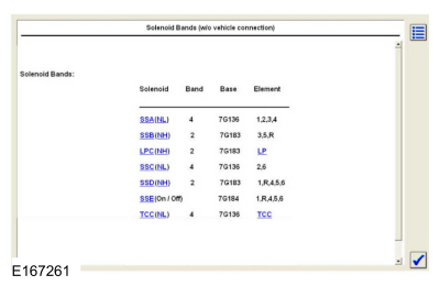
Using the scan tool Transmission Solenoid Identification
Number (IDN) function, retrieve the solenoid base part number and
stamping number.
 |
-
Remove the transmission internal wiring harness frame.
Refer to: Transmission Internal Wiring Harness Frame (307-01B Automatic Transmission - 6-Speed Automatic Transmission – 6F35, Removal and Installation).
-
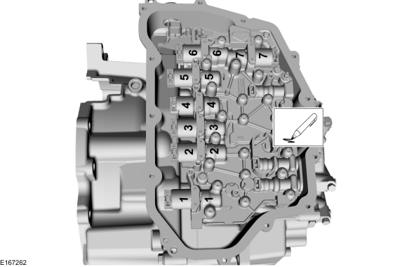
NOTICE: The solenoids are calibrated from the factory and are not all the same. Failure to install the solenoids in the ports they were originally in can result in damage to the transmission or a harsh shift.
NOTE: Note the position of the component before removal.
-
Line Pressure Control (LPC) solenoid 7G383 (high variable bleed)
-
Shift Solenoid C (SSC) 7G136 (low variable bleed)
-
TCC solenoid 7G136 (low variable bleed)
-
Shift Solenoid E (SSE) 7G484 (normally closed [OFF])
-
Shift Solenoid A (SSA) 7G136 (low variable bleed)
-
Shift Solenoid B (SSB) 7G383 (high variable bleed)
-
Shift Solenoid D (SSD) 7G383 (high variable bleed)
-
Line Pressure Control (LPC) solenoid 7G383 (high variable bleed)
 |
-
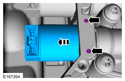
Remove the solenoid retaining pin(s) and the solenoid(s) from the solenoid body.
Use the General Equipment: Long Nose Pliers
 |
Installation
-
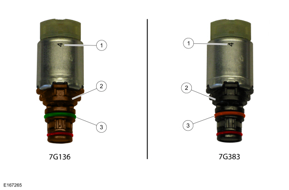
NOTE: Verify replacement component matches original component:
-
Number
-
Color
-
Color
-
Number
 |
-
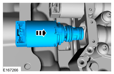
NOTE: Make sure the component is installed in the position noted before removal.
Install the solenoid(s) in the solenoid body.
 |
-
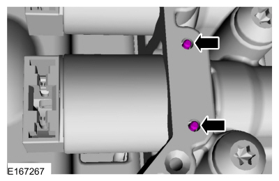
Install the solenoid retaining pin(s).
 |
-
Install the transmission internal wiring harness frame.
Refer to: Transmission Internal Wiring Harness Frame (307-01B Automatic Transmission - 6-Speed Automatic Transmission – 6F35, Removal and Installation).
 Removal and Installation - Selector Shaft Seal
Special Tool(s) /
General Equipment
307-581Manual lever seal installerTKIT-2006UF-FLMTKIT-2006UF-ROW
Flat Headed Screw Driver
Removal
Remove the TR sensor...
 Removal and Installation - Solenoid Body
Removal
To remove the solenoid body.
Refer to: Main Control Valve Body (307-01B)
.
Installation
To install, reverse the removal procedure...
Other information:
Ford Ecosport 2014-2025 Service and Repair Manual: Diagnosis and Testing - Pinpoint Test - DTC: Y
U2300:55, U2300:64 Refer to Wiring Diagrams Cell 46 for schematic and connector information. NOTE: DTC U2300:55 is set in every new RCM installed until configuration data is successfully received from the BCM . Do not install any new components for this DTC unless directed to do so in the pinpoint test...
Ford Ecosport 2014-2025 Service and Repair Manual: Removal and Installation - Front Door
Special Tool(s) / General Equipment Door Lift Removal NOTE: Removal steps in this procedure may contain installation details. NOTE: LH side shown, RH side similar. Open the front door. Remove the check arm bolt...
Copyright © 2025 www.foecosport2.com

