Ford Ecosport: Driveshaft / General Procedures - Driveshaft Angle Measurement
Check
NOTE: This procedure does not apply to CV joints, flex couplers or double cardan joints that are used in some driveshafts. This check is for single-cross and roller-style joints found in the driveshafts.
NOTE: Prior to checking driveline angularity, inspect the U-joints for correct operation.
NOTE: An incorrect driveline angle can cause a vibration or shudder.
NOTE: Driveline angularity is the angular relationship between the engine crankshaft, the driveshaft and the rear axle pinion. Factors determining driveline angularity include ride height, rear spring and engine mounts.
-
NOTE:
- Special Tool(s): Anglemaster II Driveline Inclinometer/Protractor 164-R2402. Carry out the following preliminary setup steps:
-
Inspect the U-joints for correct operation.
-
Park the vehicle on a level surface such as a drive-on hoist, or back onto a front end alignment rack.
-
Verify the curb position ride height is within
specifications with the vehicle unloaded and all of the tires are
inflated to their normal operating pressures.
-
Calibrate the Anglemaster II Driveline
Inclinometer/Protractor by placing it on a clean, flat level section of
the frame rail and press the ALT-ZERO button.
Vehicles with flat-flanged, split-pin or slip-flanged U-joints
-
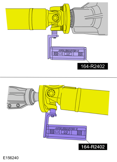
NOTE: If equipped, remove the snap ring to allow access to the base of the U-joint cup. Make sure the Anglemaster II Driveline Inclinometer/Protractor is seated against the U-joint cup.
NOTE: Rotate the driveshaft until the flange U-joint cup is parallel with the floor. This will simplify taking measurements.
Special Tool(s): Anglemaster II Driveline Inclinometer/Protractor 164-R2402. Check and record the flange angle as angle A.
 |
-
Special Tool(s): Anglemaster II Driveline
Inclinometer/Protractor 164-R2402. Measure the slope of the connecting
component. Record the measurement of the component angle as angle B.
 |
Multiple piece driveshafts
-
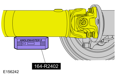
NOTE: Repeat this step for each center support bearing on the driveshaft.
NOTE: It is not necessary to remove the U-joint snap ring, if equipped, for these measurements.
Special Tool(s): Anglemaster II Driveline Inclinometer/Protractor 164-R2402. Measure the slope of the components in front and behind the center support bearing U-joint in the area indicated. Record the front component as angle A and the rear component as angle B.
 |
All vehicles
-
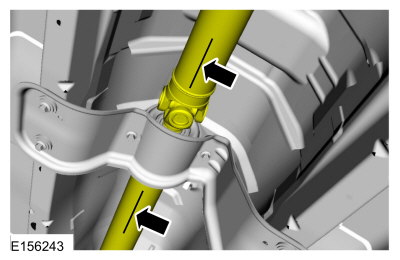
NOTE: When 2 connected components slope in the same direction, subtract the smallest number from the larger number to find the U-joint operating angle. When 2 connected components slope in the opposite direction, add the measurements to find the U-joint operating angle.
Calculate the difference in the slope of the components to determine the U-joint operating angle.
-
NOTE:
- The U-joint operating angle is the angle formed by 2 yokes connected by a cross and bearing kit. Ideally, the operating angles on each connection of the driveshaft must:
-
be equal or within one degree of each other.
-
have a 3 degree maximum operating angle.
-
have at least one-half of one degree continuous operating angle.
-
If the angle is not within specifications, repair or
adjust to obtain the correct angle. Inspect the engine mounts,
transmission mounts, center support bearing mounting, rear suspension,
rear axle, rear axle mounting or the frame for wear or damage.
 Diagnosis and Testing - Driveshaft
Symptom Chart(s)
Diagnostics in this manual assume a certain skill level and knowledge of Ford-specific diagnostic practices. REFER to: Diagnostic Methods (100-00 General Information, Description and Operation)...
 General Procedures - Driveshaft Runout and Balancing
Special Tool(s) /
General Equipment
100-002
(TOOL-4201-C)
Holding Fixture with Dial Indicator Gauge
Inspection
NOTE:
Driveline vibration exhibits a higher frequency and lower
amplitude then high-speed shake...
Other information:
Ford Ecosport 2014-2025 Service and Repair Manual: Diagnosis and Testing - Suspension System - AWD
Special Tool(s) Alignment Pins, Subframe205-870 Adapter for 205-870205-870-01 Inspection and Verification Verify the customer concern. Visually inspect for obvious signs of mechanical damage...
Ford Ecosport 2014-2025 Service and Repair Manual: Removal and Installation - Floor Console
Special Tool(s) / General Equipment Interior Trim Remover Removal NOTE: Removal steps in this procedure may contain installation details. NOTE: Console with arm rest shown, console without arm rest similar. Remove the front seats...
Categories
- Manuals Home
- 2nd Gen Ford Ecosport Service Manual (2014 - 2025)
- Removal and Installation - Catalytic Converter
- Removal and Installation - Starter Motor
- Automatic Transmission - 6-Speed Automatic Transmission – 6F35
- Diagnosis and Testing - Body Control Module (BCM)
- Body and Paint
Description and Operation - Health and Safety Precautions
General Service Warnings
Review carefully the information below before beginning any repair. Following these warnings is a list of specific system warnings that must be reviewed before beginning work on any listed system.
 WARNING:
Wear eye and ear protection when servicing a vehicle.
Failure to follow this instruction may result in serious personal
injury.
WARNING:
Wear eye and ear protection when servicing a vehicle.
Failure to follow this instruction may result in serious personal
injury.