Ford Ecosport: Glass, Frames and Mechanisms / Description and Operation - Glass, Frames and Mechanisms - System Operation and Component Description
System Operation
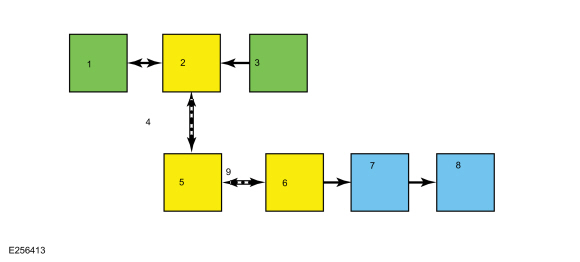
System Diagram - Rear Window Defrost (If Equipped With Touchscreen)

| Item | Description |
|---|---|
| 1 | FDIM |
| 2 | APIM |
| 3 | Microphone |
| 4 | HS-CAN3 |
| 5 | GWM |
| 6 | HVAC |
| 7 | Rear Window Defrost Relay |
| 8 | Rear Window Defrost Grid |
| 9 | MS-CAN |
Network Message Chart - Rear Window Defrost
Heating Ventilation And Air Conditioning (HVAC) Module Network Input Messages
| Broadcast Message | Originating Module | Message Purpose |
|---|---|---|
| Climate control requests | APIM (if equipped with touchscreen) | The climate control requests message contains the rear window defrost request information. When the rear window defrost function is requested using voice command or the button is selected on the touchscreen, this input activates the rear window defrost system. |
Delayed Accessory Power
Voltage is supplied to the power window system by the accessory delay relay, located in the BCM . The accessory delay relay is integral to the BCM and not serviceable separately. The BCM activates the accessory delay relay whenever the ignition is in the RUN or the ACC position, or when the ignition is changed from RUN or ACC to the OFF position and the LH and RH front doors are closed.
The BCM deactivates the accessory delay relay when:
- the LH or RH front door is ajar and the ignition is in the OFF or key-out position
- ten minutes have elapsed since the ignition was changed from ACC or RUN to the OFF position.
Power Window Operation
The power windows operate when the ignition is on or the accessory delay feature is active. The accessory delay feature allows the windows to function for several minutes after the ignition is turned off or until a front door is opened.
Driver Door Window Operation
The master window control switch contains electronics that control the one-touch up/down operation. The master window control switch receives feedback from the Hall-effect sensors which are integral to the driver front window regulator motor. If the Hall-effect sensors or any associated circuitry fails, the window still operates but the one-touch up/down and obstacle detection is inoperative.
If an obstacle has been detected in the window opening as the door window glass is moving upward, the window motor automatically reverses direction and moves the glass toward the bounce-back position.
To override a bounce-back condition (for example, to overcome the resistance of ice on the window or seals), close the window glass twice until it reaches the resistance and allow it to reverse to the bounce-back position. On the third attempt, activate and hold the master window control switch in the UP position. The window travels up with no bounce-back protection
Passenger Door Window Operation
The window control switch can be used to manually raise or lower all windows from the master window control switch or the individual side window from the corresponding individual door switch.
Passenger Windows Lock-Out
When the lock-out switch (part of the master window control switch) is in the LOCK position, the rear door passenger power windows can only be operated from the master window control switch.
Rear Window Defrost
When the rear window defrost switch (integral to the HVAC module) is activated, the HVAC module activates the rear window defrost relay (located in the BJB ).
If equipped with a touchscreen, the rear window defrost can also be commanded on and off using voice commands or by touching the rear window defrost button located on the touchscreen (FDIM ). For additional information on voice or touchscreen commanded features, refer to the Owner's Literature.
The HVAC module deactivates the rear window defrost relay when any one of these conditions is met:
- The rear window defrost switch is pressed when the feature is active.
- If equipped, the rear window defrost is commanded off using voice command or the touchscreen interface when the feature is active.
- Ignition state is changed from ON to OFF.
- A predetermined timer completes.
- Battery voltage has dropped below a specified threshold (load management strategy).
Component Description
Master Window Control Switch
The master window control switch and the driver front window motor each contain integral electronics which must be initialized whenever:
- a new master window control switch is installed.
- a new driver door window regulator and motor is installed.
- a new driver door window glass is installed.
- carrying out any operation in which grease or lubricants are applied to the driver door window system.
- battery voltage has been removed from the master window control switch for more than 3 minutes (for example, battery or window control switch disconnected).
Refer to: Power Door Window Initialization (501-11 Glass, Frames and Mechanisms, General Procedures).
The master window control switch:
- is supplied voltage when the ignition is on or the accessory delay feature is active.
- contains integral electronics to control the one-touch up/down operation of the driver door window.
- supplies high current voltage and ground directly to the driver front power window motor to move the window upward and downward.
- supplies low current voltage to the rear power windows when the lock-out switch is in the UNLOCK position.
Passenger Door Window Control Switch
The passenger door window control switch receives voltage (high current circuit) from the delayed accessory relay whenever it is active. The passenger door window control switch contacts are normally closed. The passenger door window control switch has a dedicated ground circuit. The passenger door window control switch contains relays, which when at rest (inactive), provide a ground path to their respective door window motor circuit(s).
When the passenger door window control switch is activated, the corresponding relay located within the rear door window control switch is energized which supplies voltage (high current) to operate the door window motor in the desired direction.
Rear Door Window Control Switch
The rear door window control switches receive voltage (high current circuit) from the delayed accessory relay whenever it is active. The rear door window control switches receive voltage (low current circuit) from the master window control switch when the lock-out switch is in the UNLOCK position. The rear door window control switches each have a dedicated ground circuit. The rear door window control switches contain relays, which when at rest (inactive), provide a ground path to their respective door window motor circuit(s).
When a rear door window control switch is activated, the corresponding relay located within the rear door window control switch is energized which supplies voltage (high current) to operate the door window motor in the desired direction.
Driver Door Window Regulator Motor
The driver window regulator motor contains 2 Hall-effect sensors which provide feedback to the master window control switch. The driver window regulator motor is bi-directional. Window direction is determined by the polarity of the voltage and ground being supplied to the motor from the master window control switch.
Door Window Regulator Motor
The window regulator motors are all bi-directional. Window direction is determined by the polarity of the voltage and ground being supplied to the motor from the door window control switch.
HVAC Module
The HVAC module contains the rear window defrost button and also controls the rear window defrost relay. The HVAC module requires PMI when it is replaced.
BCM
The BCM module controls the accessory delay relay which supplies voltage to operate the power window system. The BCM module requires PMI when it is replaced.
 Description and Operation - Glass, Frames and Mechanisms - Overview
Overview
Delayed Accessory Feature
The
power windows operate only when the delayed accessory feature is
active. The delayed accessory feature is active whenever the ignition is
ON, or up to 10 minutes after the ignition is changed from ON to OFF
while the driver and passenger doors remain closed...
 Diagnosis and Testing - Glass, Frames and Mechanisms
DTC Chart: HVAC Module
Diagnostics in this manual assume a certain skill level and knowledge of Ford-specific diagnostic practices. REFER to: Diagnostic Methods (100-00 General Information, Description and Operation)...
Other information:
Ford Ecosport 2014-2024 Service and Repair Manual: Diagnosis and Testing - Fog Lamps
DTC Chart: BCM Diagnostics in this manual assume a certain skill level and knowledge of Ford-specific diagnostic practices. REFER to: Diagnostic Methods (100-00 General Information, Description and Operation). DTC Description Action B1046:11 Front Fog Lamp Control Switch: Circuit Short To Ground ..
Ford Ecosport 2014-2024 Service and Repair Manual: Description and Operation - Glass, Frames and Mechanisms - Overview
Overview Delayed Accessory Feature The power windows operate only when the delayed accessory feature is active. The delayed accessory feature is active whenever the ignition is ON, or up to 10 minutes after the ignition is changed from ON to OFF while the driver and passenger doors remain closed. Power Window Operation Standard power window features include one-touch ..
Categories
- Manuals Home
- 2nd Gen Ford Ecosport Service Manual (2014 - 2024)
- Anti-Lock Brake System (ABS) and Stability Control
- Removal and Installation - Block Heater
- Removal and Installation - Fuel Filler Door Assembly
- General Procedures - Transmission Fluid Level Check
- Removal and Installation - Fuel Pump and Sender Unit
Removal and Installation - Wheel Knuckle Bushing
Special Tool(s) / General Equipment
Hydraulic PressRemoval
NOTE: Removal steps in this procedure may contain installation details.
Remove the wheel knuckle.Refer to: Wheel Knuckle - Vehicles With: Rear Drum Brakes (204-02B Rear Suspension - AWD, Removal and Installation).
Remove the rear toe adjustment retainers and remove the wheel knuckle mounting bracket.
Torque:
Stage 1: 177 lb.in (20 Nm)
Stage 2: 76 lb.ft (103 Nm)