Ford Ecosport: Module Communications Network / Description and Operation - Communications Network - System Operation and Component Description
System Operation
System Operation
*.sttxt { visibility: hidden; } *.stcallout { visibility: visible; } E356703 1 IPC 2 ACM 3 DSP 4 HVAC 5 TRM 6 PDM 7 SOD-L 8 SOD-R 9 DDM 10 PCM 11 BCM 12 PAM 13 BECMB 14 SCCM 15 PSCM 16 RCM 17 ABS 18 OCS 19 Gateway Module 20 TCU 21 APIM| Item | Description |
|---|---|
| 1 | IPC |
| 2 | ACM |
| 3 | DSP |
| 4 | HVAC |
| 5 | TRM |
| 6 | PDM |
| 7 | SODL |
| 8 | SODR |
| 9 | DDM |
| 10 | PCM |
| 11 | BCM |
| 12 | PAM |
| 13 | BECMB |
| 14 | SCCM |
| 15 | PSCM |
| 16 | RCM |
| 17 | ABS ABS |
| 18 | OCS |
| 19 | GWM |
| 20 | TCU |
| 21 | APIM |
Module Network Chart
| Module Name | Network Type | Terminating Module |
|---|---|---|
| APIM | HS-CAN1 | No |
| HS-CAN3 | No | |
| HS-CAN4 | No | |
| ABS module | HS-CAN2 | No |
| ACM | HS-CAN3 | No |
| BCM | HS-CAN1 | No |
| BECMB | HS-CAN1 | No |
| DDM | MS-CAN | No |
| DSP (if equipped) | HS-CAN3 | No |
| GWM | HS-CAN1 | Yes |
| HS-CAN2 | Yes | |
| HS-CAN3 | Yes | |
| HS-CAN4 | Yes | |
| MS-CAN | Yes | |
| HVAC module | MS-CAN | Yes |
| IPC | HS-CAN3 | Yes |
| OCS module | HS-CAN2 | No |
| PAM | HS-CAN1 | No |
| PDM | MS-CAN | No |
| PSCM | HS-CAN2 | No |
| PCM | HS-CAN1 | Yes |
| RCM | HS-CAN2 | No |
| SCCM | HS-CAN2 | Yes |
| SODL (if equipped) | MS-CAN | No |
| SODR (if equipped) | MS-CAN | No |
| TCU (if equipped) | HS-CAN4 | Yes |
| TRM (if equipped) | MS-CAN | No |
Network Termination
The CAN uses network termination to improve communication reliability. Termination modules are located at both ends of the network. As network messages are broadcast in the form of voltage signals, the network voltage signals are stabilized by the termination resistors.
Each termination module has an internal 120 ohm resistor that bridges across the positive and negative bus connection. With two 120 ohm resistors located in a parallel circuit configuration, the total network impedance, or total resistance, is 60 ohms.
Network termination improves bus message reliability by stabilizing bus voltage and eliminating electrical interference.
Gateway Module
NOTE: The GWM communicates with the 4 or 5 (optional) controller area networks (CANs). The OBD DLC is fitted to the GWM and is the interface with the diagnostic scan tool.
The GWM is mounted under the driver side instrument panel. The OBD connector is fitted to the GWM . The GWM acts as a central gateway to translate messages across all vehicle controller area networks (CANs), and vice versa. The GWM is the only module on the vehicle with this ability. The GWM also serves as a termination module for each of the networks to which it is connected.
The 2 module communication networks connected to the DLC are DIAG 1 and DIAG 2. These 2 networks communicate directly with the diagnostic scan tool. The other communication networks, communicate on the network, but do not communicate directly with the diagnostic scan tool. The GWM translates the messages from the HS-CAN1 to DIAG 1. The GWM translates messages from the HS-CAN2 , HS-CAN3 , HS-CAN4 (if equipped) and MS-CAN to DIAG 2 which transfers the signals to the diagnostic scan tool.

| Item | Description |
|---|---|
| 1 | DIAG 1 |
| 2 | DIAG 2 |
| 3 | GWM |
| 4 | Transceiver |
| 5 | DLC |
| 6 | DIAG 2 Transceiver |
| 7 | DIAG 1 Transceiver |
| 8 | Transceiver |
| 9 | Transceiver |
| 10 | Transceiver |
| 11 | Transceiver |
High Speed Controller Area Network 1 and 2 (HS-CAN1, HS-CAN2)
The HS-CAN1 and HS-CAN2 operate at a maximum data transfer speed of 500 Kbps and are designed for real time powertrain and driver feature information transfer and control. Modules on the HS-CAN1 and HS-CAN2 communicate using bussed messages. The HS-CAN uses an unshielded twisted pair cable, data bus (+) and data bus (-) circuits. In addition to diagnostic scan tool communication, the HS-CAN allows sharing of information between all modules on each HS-CAN .
With the addition of more modules, network traffic has increased. This has created the need for an additional HS-CAN to manage the increased bus data carried on each network.
The GWM translates the diagnostic messages from the DIAG 1 network to the HS-CAN1 and vice versa, allowing communication between the modules on the HS-CAN1 and diagnostic scan tool. The GWM translates the diagnostic messages from the DIAG 2 network to the HS-CAN2 and vice versa, allowing communication between the modules on the HS-CAN2 and diagnostic scan tool.
High Speed Controller Area Network 3 and 4 (HS-CAN3, HS-CAN4)
The HS-CAN3 and HS-CAN4 (if equipped) operate at a maximum data transfer speed of 500 Kbps and are designed for real time audio, multimedia and driver information transfer and control. Modules on the HS-CAN3 and HS-CAN4 (if equipped) communicate using bussed messages. HS-CAN3 and HS-CAN4 (if equipped) use an unshielded twisted pair cable, data bus (+) and data bus (-) circuits, and allows sharing of information between all modules on the network.
The GWM is used as a gateway for the messages to transfer between the diagnostic scan tool and the modules on the HS-CAN3 and HS-CAN4 (if equipped).
The GWM translates the diagnostic messages from the DIAG 2 to the HS-CAN3 and HS-CAN4 (if equipped) and vice versa, allowing communication between the modules on the HS-CAN3 and HS-CAN4 (if equipped) and the diagnostic scan tool.
Medium Speed Controller Area Network (MS-CAN)
The MS-CAN operates at a maximum data transfer speed of 125 Kbps and is designed for general information transfer. Modules on the MS-CAN communicate using bussed messages. The MS-CAN uses an unshielded twisted pair cable, data bus (+) and data bus (-) circuits. In addition to diagnostic scan tool communication, the MS-CAN allows sharing of information between all modules on the network.
The GWM is used as a gateway for the messages to transfer between the diagnostic scan tool and the modules on the MS-CAN .
The GWM translates the diagnostic messages from the DIAG 2 to the MS-CAN and vice versa, allowing communication between the modules on the MS-CAN and the diagnostic scan tool.
Controller Area Network (CAN) Fault Tolerance
NOTE: IDS shown, Ford Diagnostic Retrieval System (FDRS) similar.
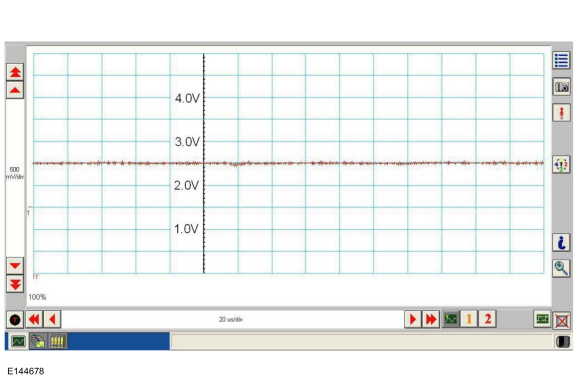
NOTE: The oscilloscope traces shown are from the IDS oscilloscope taken using the IDS pre-configured CAN settings. The traces are for both data (+) and data (-) taken simultaneously (2-channel) at a sample rate of 1 mega-sample per second (1MS/s) or greater.
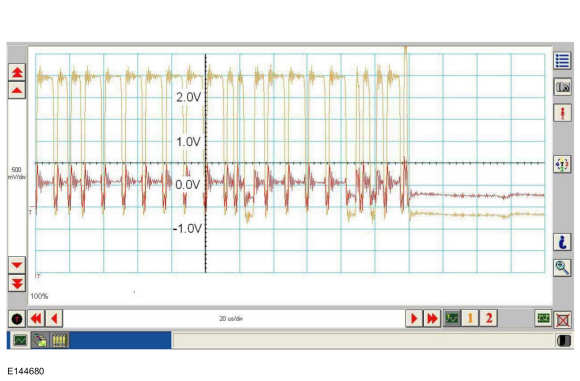
Fault Tolerance Normal Operation

The data (+) and data (-) circuits are each regulated to approximately 2.5 volts during neutral or rested network traffic. As messages are sent on the data (+) circuit, voltage is increased by approximately 1.0 volt. Inversely, the data (-) circuit is reduced by approximately 1.0 volt when a message is sent.
Successful communication of a message can usually be identified by the slight spike at the end of a message transmission. Any signals that are significantly different than the normal CAN waveform may cause network Diagnostic Trouble Codes (DTCs) (U-codes) to set or may cause a complete network outage.
CAN Circuits Shorted Together
In the event the data (+) and data (-) circuits become shorted together, the signal stays at base voltage (2.5V) continuously and all communication capabilities are lost.
CAN (+) Circuit Shorted to Ground

In the event the data (+) circuit becomes shorted to ground, both the data (+) and data (-) circuits are pulled low (0V) and all communication capabilities are lost.
CAN (-) Circuit Shorted to Ground
In the event the data (-) circuit becomes shorted to ground, the data (-) circuit is pulled low (0V) and the data (+) circuit reaches near-normal peak voltage (3.0V) during communication but falls to 0V instead of normal base voltage (2.5V). Communication may continue but at a degraded level.
CAN (+) Circuit Shorted to Battery Voltage

In the event the data (+) circuit becomes shorted to battery voltage, the data (+) circuit is pulled high (12V) and the data (-) circuit falls to abnormally high voltage (above 5V) during communication and reaches battery voltage (12V) for peak voltage. Communication may continue but at a degraded level.
CAN (-) Circuit Shorted to Battery Voltage

In the event the data (-) circuit becomes shorted to battery voltage, both the data (+) and data (-) circuits are pulled high (12V) and all communication capabilities are lost.
CAN Circuit Signal Corruption

Rhythmic oscillations, inductive spikes or random interference can corrupt the network communications. The corruption signal source may be outside electrical interference such as motors or solenoids or internal interference generated from a module on the network. In some cases, an open in either the data (+) or data (-) circuit to a network module may cause the module to emit interference on the one circuit which is still connected. The trace shown is an example of a "sawtooth" pattern transmitted from a module with one open network circuit.
Other corruptions may be present when a module is intermittently powered up and down. The module on power up may initiate communication out of sync with other modules on the network causing momentary communication outages.
Controller Area Network (CAN) Multiplex Messages
| Network Message | Originating Module | Network Type | Receiving Module(s) |
|---|---|---|---|
| A/C clutch status | PCM | HS-CAN1 |
|
| A/C clutch status | GWM | HS-CAN3 |
|
| A/C clutch status | GWM | MS-CAN |
|
| A/C clutch status | GWM | HS-CAN4 |
|
| ABS active | ABS module | HS-CAN2 |
|
| ABS active | GWM | HS-CAN1 |
|
| ABS active | GWM | HS-CAN4 |
|
| ABS fault | ABS module | HS-CAN2 |
|
| ABS fault | GWM | HS-CAN1 |
|
| ABS fault | GWM | HS-CAN3 |
|
| ABS fault | GWM | HS-CAN4 |
|
| ABS warning indicator request | ABS module | HS-CAN2 |
|
| ABS warning indicator request | GWM | HS-CAN3 |
|
| ABS warning indicator request | GWM | HS-CAN4 |
|
| Accelerator pedal position | PCM | HS-CAN1 |
|
| Accelerator pedal position | GWM | HS-CAN2 |
|
| Accelerator pedal position | GWM | HS-CAN3 |
|
| Accelerator pedal position | GWM | HS-CAN4 |
|
| Accelerator pedal position | GWM | MS-CAN |
|
| Accessory delay | BCM | HS-CAN1 |
|
| Accessory delay | GWM | HS-CAN3 |
|
| Accessory delay | GWM | HS-CAN4 |
|
| Accessory delay | GWM | MS-CAN |
|
| ACM track information | ACM | HS-CAN3 |
|
| Airbag deployment status | RCM | HS-CAN2 |
|
| Airbag deployment status | GWM | HS-CAN1 |
|
| Airbag indicator status | IPC | HS-CAN3 |
|
| Airbag indicator status | GWM | HS-CAN2 |
|
| Airbag warning indicator request | RCM | HS-CAN2 |
|
| Airbag warning indicator request | GWM | HS-CAN3 |
|
| Airbag warning indicator request | GWM | HS-CAN4 |
|
| Ambient air temperature | PCM | HS-CAN1 |
|
| Ambient air temperature | GWM | MS-CAN |
|
| Ambient air temperature | GWM | HS-CAN3 |
|
| Ambient air temperature | GWM | HS-CAN2 |
|
| Ambient air temperature | GWM | HS-CAN4 |
|
| Ambient air temperature filtered | PCM | HS-CAN1 |
|
| Ambient air temperature filtered | GWM | MS-CAN |
|
| Ambient air temperature filtered | GWM | HS-CAN3 |
|
| Ambient air temperature filtered | GWM | HS-CAN4 |
|
| Ambient light color/intensity | BCM | HS-CAN1 |
|
| Ambient light color/intensity | GWM | HS-CAN3 |
|
| Ambient light color/intensity request | APIM | HS-CAN3 |
|
| Ambient light color/intensity request | GWM | HS-CAN1 |
|
| Ambient light color/intensity request | GWM | HS-CAN4 |
|
| Ambient light sensor | SCCM | HS-CAN2 |
|
| Ambient light sensor | GWM | HS-CAN1 |
|
| Audio chime status | ACM | HS-CAN3 |
|
| Audio settings | IPC | HS-CAN3 |
|
| Audio source status | ACM | HS-CAN3 |
|
| Audio source status | GWM | HS-CAN4 |
|
| Audio system response status | ACM | HS-CAN3 |
|
| AWD lock request | ABS module | HS-CAN2 |
|
| AWD lock request | GWM | HS-CAN1 |
|
| AWD lock status | PCM | HS-CAN1 |
|
| AWD lock status | GWM | HS-CAN2 |
|
| AWD service required | PCM | HS-CAN1 |
|
| AWD service required | GWM | HS-CAN2 |
|
| AWD service required | GWM | HS-CAN3 |
|
| AWD status | PCM | HS-CAN1 |
|
| AWD status | GWM | HS-CAN3 |
|
| Backlit LED status | BCM | HS-CAN1 |
|
| Backlit LED status | GWM | HS-CAN3 |
|
| Backlit LED status | GWM | HS-CAN4 |
|
| Backlit LED status | GWM | MS-CAN |
|
| Battery low state of charge | BCM | HS-CAN1 |
|
| Battery low state of charge | GWM | MS-CAN |
|
| Battery low state of charge | GWM | HS-CAN3 |
|
| Battery low state of charge | GWM | HS-CAN4 |
|
| Beltminder audio mute | ACM | HS-CAN3 |
|
| BLIS / CTA enable request | IPC | HS-CAN3 |
|
| BLIS / CTA enable request | GWM | MS-CAN |
|
| BLIS / CTA LED command - left | SODL | MS-CAN |
|
| BLIS / CTA LED command - right | SODR | MS-CAN |
|
| BLIS / CTA LED command | GWM | HS-CAN3 |
|
| Bluetooth call request | IPC | HS-CAN3 |
|
| Body service required request | BCM | HS-CAN1 |
|
| Body service required request | GWM | HS-CAN3 |
|
| Brake (red) warning indicator request | ABS module | HS-CAN2 |
|
| Brake (red) warning indicator request | GWM | HS-CAN3 |
|
| Brake (red) warning indicator request | GWM | HS-CAN1 |
|
| Brake (red) warning indicator request | GWM | HS-CAN4 |
|
| Brake pedal applied message request | PCM | HS-CAN1 |
|
| Brake pedal applied message request | GWM | HS-CAN3 |
|
| Brake pedal applied message request | GWM | HS-CAN4 |
|
| Call options | IPC | HS-CAN3 |
|
| Camera settings | BCM | HS-CAN1 |
|
| Camera settings | GWM | HS-CAN3 |
|
| Camera settings | GWM | HS-CAN4 |
|
| Camera status | IPC | HS-CAN3 |
|
| Camera status | GWM | HS-CAN1 |
|
| Camera status | GWM | HS-CAN4 |
|
| CD load/eject | ACM | HS-CAN3 |
|
| Cell phone chirp request | TCU | HS-CAN4 |
|
| Cell phone chirp request | GWM | HS-CAN1 |
|
| Cell phone lock request | TCU | HS-CAN4 |
|
| Cell phone lock request | GWM | HS-CAN1 |
|
| Center stack display configuration | APIM | HS-CAN1 |
|
| Center stack display configuration | GWM | HS-CAN2 |
|
| Center stack display configuration | GWM | MS-CAN |
|
| Center stack display configuration | GWM | HS-CAN3 |
|
| Center stack display configuration | GWM | HS-CAN4 |
|
| Check fuel fill inlet message request | PCM | HS-CAN1 |
|
| Check fuel fill inlet message request | GWM | HS-CAN3 |
|
| Check fuel fill inlet message request | GWM | HS-CAN4 |
|
| Chime controls | IPC | HS-CAN3 |
|
| Chime module power up | IPC | HS-CAN3 |
|
| Chime source | IPC | HS-CAN3 |
|
| Climate control button status | HVAC module | MS-CAN |
|
| Climate control button status | GWM | HS-CAN3 |
|
| Crash event status | BCM | HS-CAN1 |
|
| Crash event status | GWM | MS-CAN |
|
| Crash event status | GWM | HS-CAN4 |
|
| Cross traffic alert left status | SODL | MS-CAN |
|
| Cross traffic alert left status | GWM | HS-CAN3 |
|
| Cross traffic alert right status | SODR | MS-CAN |
|
| Cross traffic alert right status | GWM | HS-CAN3 |
|
| Cross traffic left sensor status | SODL | MS-CAN |
|
| Cross traffic left sensor status | GWM | HS-CAN3 |
|
| Cross traffic right sensor status | SODR | MS-CAN |
|
| Cross traffic right sensor status | GWM | HS-CAN3 |
|
| Cruise control disable command | ABS module | HS-CAN2 |
|
| Cruise control disable command | GWM | HS-CAN1 |
|
| Cruise control mode | PCM | HS-CAN1 |
|
| Cruise control mode | GWM | HS-CAN2 |
|
| Cruise control mode | GWM | HS-CAN4 |
|
| Cruise control override | PCM | HS-CAN1 |
|
| Cruise control override | GWM | HS-CAN2 |
|
| Cruise control override | GWM | HS-CAN3 |
|
| Cruise control override | GWM | HS-CAN4 |
|
| Cruise control set speed display | PCM | HS-CAN1 |
|
| Cruise control set speed display | GWM | HS-CAN3 |
|
| Cruise control set speed display | GWM | HS-CAN4 |
|
| Cruise control set vehicle speed request | PCM | HS-CAN1 |
|
| Cruise control set vehicle speed request | GWM | HS-CAN3 |
|
| Cruise control set vehicle speed request | GWM | HS-CAN4 |
|
| Cruise control status | PCM | HS-CAN1 |
|
| Cruise control status | GWM | HS-CAN2 |
|
| Cruise control status | GWM | HS-CAN3 |
|
| Cruise control status | GWM | HS-CAN4 |
|
| Cruise control switch commands | SCCM | HS-CAN2 |
|
| Cruise control switch commands | GWM | HS-CAN1 |
|
| Date/time adjustment | APIM | HS-CAN3 |
|
| Date/time settings | APIM | HS-CAN3 |
|
| Day/night status | BCM | HS-CAN1 |
|
| Day/night status | GWM | HS-CAN3 |
|
| Day/night status | GWM | MS-CAN |
|
| Day/night status | GWM | HS-CAN2 |
|
| Day/night status | GWM | HS-CAN4 |
|
| Daytime running lamps status | BCM | HS-CAN1 |
|
| Daytime running lamps status | GWM | HS-CAN3 |
|
| Daytime running lamps status | GWM | HS-CAN4 |
|
| Display language request | APIM | HS-CAN3 |
|
| Display language select | APIM | HS-CAN3 |
|
| Display speed offset data | IPC | HS-CAN3 |
|
| Display speed offset data | GWM | HS-CAN1 |
|
| Do not disturb override status | IPC | HS-CAN3 |
|
| Driver door ajar status | BCM | HS-CAN1 |
|
| Driver door ajar status | GWM | HS-CAN3 |
|
| Driver door ajar status | GWM | HS-CAN2 |
|
| Driver door ajar status | GWM | HS-CAN4 |
|
| Driver door ajar status | GWM | MS-CAN |
|
| Driver seat belt buckle status | RCM | HS-CAN2 |
|
| Driver seat belt buckle status | GWM | HS-CAN3 |
|
| Driver seat belt buckle status | GWM | HS-CAN1 |
|
| Driver seat belt buckle status | GWM | HS-CAN4 |
|
| Driver set temperature | APIM | HS-CAN3 |
|
| Driver set temperature | GWM | MS-CAN |
|
| DSP chime request | DSP | HS-CAN3 |
|
| DSP volume status | DSP | HS-CAN3 |
|
| eCall confirmation | APIM | HS-CAN1 |
|
| eCall confirmation | GWM | HS-CAN2 |
|
| eCall notification | RCM | HS-CAN2 |
|
| eCall notification | GWM | HS-CAN1 |
|
| eCall notification | GWM | HS-CAN4 |
|
| Emergency assist active status | ACM | HS-CAN3 |
|
| Emergency assist active status | GWM | HS-CAN1 |
|
| Emergency brake lamp request | ABS module | HS-CAN2 |
|
| Emergency brake lamp request | GWM | HS-CAN1 |
|
| Emergency brake lamp request | GWM | HS-CAN4 |
|
| Emergency call mute status | TCU | HS-CAN4 |
|
| Emergency call mute status | GWM | HS-CAN3 |
|
| Engine coolant temperature | PCM | HS-CAN1 |
|
| Engine coolant temperature | GWM | MS-CAN |
|
| Engine coolant temperature | GWM | HS-CAN2 |
|
| Engine coolant temperature | GWM | HS-CAN3 |
|
| Engine coolant temperature | GWM | HS-CAN4 |
|
| Engine exhaust over temperature display | PCM | HS-CAN1 |
|
| Engine exhaust over temperature display | GWM | HS-CAN3 |
|
| Engine idle shutdown request | IPC | HS-CAN3 |
|
| Engine idle shutdown request | GWM | HS-CAN1 |
|
| Engine idle shutdown request | GWM | HS-CAN4 |
|
| Engine idle shutdown status | PCM | HS-CAN1 |
|
| Engine idle shutdown status | GWM | HS-CAN3 |
|
| Engine idle shutdown status | GWM | HS-CAN4 |
|
| Engine oil level warning indicator | PCM | HS-CAN1 |
|
| Engine oil level warning indicator | GWM | HS-CAN3 |
|
| Engine oil life | PCM | HS-CAN1 |
|
| Engine oil life | GWM | HS-CAN3 |
|
| Engine oil life | GWM | HS-CAN4 |
|
| Engine oil life data reset | IPC | HS-CAN3 |
|
| Engine oil life data reset | GWM | HS-CAN1 |
|
| Engine oil temperature | PCM | HS-CAN1 |
|
| Engine oil temperature | GWM | HS-CAN3 |
|
| Engine overheat indication request | PCM | HS-CAN1 |
|
| Engine overheat indication request | GWM | HS-CAN3 |
|
| Engine overheat indication request | GWM | HS-CAN4 |
|
| Engine rpm data | PCM | HS-CAN1 |
|
| Engine rpm data | GWM | HS-CAN2 |
|
| Engine rpm data | GWM | HS-CAN3 |
|
| Engine rpm data | GWM | HS-CAN4 |
|
| Engine service required request | PCM | HS-CAN1 |
|
| Engine service required request | GWM | HS-CAN3 |
|
| Engine service required request | GWM | HS-CAN2 |
|
| Engine service required request | GWM | HS-CAN4 |
|
| Engine status | PCM | HS-CAN1 |
|
| Engine status | GWM | HS-CAN3 |
|
| Engine status | GWM | HS-CAN2 |
|
| Engine status | GWM | HS-CAN4 |
|
| Engine status | GWM | MS-CAN |
|
| English/metric mode | IPC | HS-CAN3 |
|
| English/metric mode | GWM | MS-CAN |
|
| English/metric mode | GWM | HS-CAN1 |
|
| EPAS failure | PSCM | HS-CAN2 |
|
| EPAS failure | GWM | HS-CAN3 |
|
| EPAS failure | GWM | HS-CAN4 |
|
| ePRNDL mode | IPC | HS-CAN3 |
|
| ePRNDL mode | GWM | HS-CAN1 |
|
| Factory mode | BCM | HS-CAN1 |
|
| Factory mode | GWM | HS-CAN2 |
|
| Factory mode | GWM | MS-CAN |
|
| Factory mode | GWM | HS-CAN3 |
|
| Factory mode | GWM | HS-CAN4 |
|
| Front blower speed | APIM | HS-CAN3 |
|
| Front blower speed | GWM | MS-CAN |
|
| Front fog lamp indicator request | BCM | HS-CAN1 |
|
| Front fog lamp indicator request | GWM | HS-CAN3 |
|
| Front fog lamp indicator request | GWM | HS-CAN4 |
|
| Front passenger detect status | RCM | HS-CAN2 |
|
| Front passenger detect status | GWM | HS-CAN3 |
|
| Front passenger detect status | GWM | HS-CAN4 |
|
| Front wiper status | SCCM | HS-CAN2 |
|
| Front wiper status | GWM | HS-CAN3 |
|
| Front wiper status | GWM | MS-CAN |
|
| Front wiper status | GWM | HS-CAN1 |
|
| Front wiper status | GWM | HS-CAN4 |
|
| Frost warning indicator | IPC | HS-CAN3 |
|
| Frost warning indicator | GWM | HS-CAN1 |
|
| Fuel alcohol percent | PCM | HS-CAN1 |
|
| Fuel alcohol percent | GWM | HS-CAN3 |
|
| Fuel fill inlet message display | PCM | HS-CAN1 |
|
| Fuel fill inlet message display | GWM | HS-CAN3 |
|
| Fuel flow volume display | PCM | HS-CAN1 |
|
| Fuel flow volume display | GWM | HS-CAN3 |
|
| Fuel flow volume display | GWM | HS-CAN4 |
|
| Gear lever position | PCM | HS-CAN1 |
|
| Gear lever position | GWM | HS-CAN2 |
|
| Gear lever position | GWM | HS-CAN3 |
|
| Gear lever position | GWM | HS-CAN4 |
|
| Gear lever position | GWM | MS-CAN |
|
| Global clock | BCM | HS-CAN1 |
|
| Global clock | GWM | HS-CAN3 |
|
| Global clock | GWM | HS-CAN4 |
|
| Global clock | GWM | MS-CAN |
|
| GPS compass direction | APIM | HS-CAN3 |
|
| GPS tracking request | TCU | HS-CAN4 |
|
| GPS tracking request | GWM | HS-CAN3 |
|
| Grill shutter position command | PCM | HS-CAN1 |
|
| Grill shutter position command | GWM | HS-CAN3 |
|
| Grill shutter position command | GWM | HS-CAN4 |
|
| Headlamp flash to pass status | SCCM | HS-CAN2 |
|
| Headlamp flash to pass status | GWM | HS-CAN1 |
|
| Headlamp high/low status | BCM | HS-CAN1 |
|
| Headlamp high/low status | GWM | HS-CAN3 |
|
| Headlamp high/low status | GWM | HS-CAN4 |
|
| Headlamp low beam out | BCM | HS-CAN1 |
|
| Headlamp low beam out | GWM | HS-CAN3 |
|
| Headlamp low beam out | GWM | HS-CAN4 |
|
| Headlamp on warning chime | BCM | HS-CAN1 |
|
| Headlamp on warning chime | GWM | HS-CAN3 |
|
| Headlamp on warning chime | GWM | HS-CAN4 |
|
| Hill start assist display | ABS module | HS-CAN2 |
|
| Hill start assist display | GWM | HS-CAN3 |
|
| Hill start assist mode request | IPC | HS-CAN3 |
|
| Hill start assist mode request | GWM | HS-CAN2 |
|
| Hill start assist status | ABS module | HS-CAN2 |
|
| Hill start assist status | GWM | HS-CAN1 |
|
| Hill start assist status | GWM | HS-CAN3 |
|
| Hill start assist status | GWM | HS-CAN4 |
|
| Home safe lamp indicator request | BCM | HS-CAN1 |
|
| Home safe lamp indicator request | GWM | HS-CAN3 |
|
| Home safe lamp indicator request | GWM | HS-CAN4 |
|
| Hood ajar status | BCM | HS-CAN1 |
|
| Hood ajar status | GWM | HS-CAN2 |
|
| Hood ajar status | GWM | HS-CAN3 |
|
| Hood ajar status | GWM | HS-CAN4 |
|
| HVAC A/C request | HVAC module | MS-CAN |
|
| HVAC A/C request | GWM | HS-CAN1 |
|
| HVAC front/rear blower status | HVAC module | MS-CAN |
|
| HVAC front/rear blower status | GWM | HS-CAN1 |
|
| HVAC evap temperature | HVAC module | MS-CAN |
|
| HVAC evap temperature | GWM | HS-CAN1 |
|
| Ignition key type | BCM | HS-CAN1 |
|
| Ignition key type | GWM | HS-CAN3 |
|
| Ignition key type | GWM | MS-CAN |
|
| Ignition key type | GWM | HS-CAN2 |
|
| Ignition key type | GWM | HS-CAN4 |
|
| Ignition status | BCM | HS-CAN1 |
|
| Ignition status | GWM | MS-CAN |
|
| Ignition status | GWM | HS-CAN2 |
|
| Ignition status | GWM | HS-CAN3 |
|
| Ignition status | GWM | HS-CAN4 |
|
| Illumination dimming level | BCM | HS-CAN1 |
|
| Illumination dimming level | GWM | MS-CAN |
|
| Illumination dimming level | GWM | HS-CAN3 |
|
| Illumination dimming level | GWM | HS-CAN4 |
|
| Immobilizer message display | BCM | HS-CAN1 |
|
| Immobilizer message display | GWM | HS-CAN3 |
|
| Input controller interface button data | SCCM | HS-CAN2 |
|
| Input controller interface button data | GWM | HS-CAN3 |
|
| IPC chime request | IPC | HS-CAN3 |
|
| Key in ignition status | BCM | HS-CAN1 |
|
| Key in ignition status | GWM | HS-CAN3 |
|
| Key in ignition status | GWM | HS-CAN2 |
|
| Key in ignition status | GWM | HS-CAN4 |
|
| Key-in-ignition indicator status | BCM | HS-CAN1 |
|
| Key-in-ignition indicator status | GWM | HS-CAN3 |
|
| Key-in-ignition indicator status | GWM | HS-CAN4 |
|
| Language selection | IPC | HS-CAN3 |
|
| Language selection | GWM | HS-CAN4 |
|
| Language update status | IPC | HS-CAN3 |
|
| Language update status | GWM | HS-CAN4 |
|
| Left rear door ajar status | BCM | HS-CAN1 |
|
| Left rear door ajar status | GWM | HS-CAN2 |
|
| Left rear door ajar status | GWM | HS-CAN3 |
|
| Left rear door ajar status | GWM | HS-CAN4 |
|
| Left rear door ajar status | GWM | MS-CAN |
|
| Left turn lamp on request | BCM | HS-CAN1 |
|
| Left turn lamp on request | GWM | HS-CAN3 |
|
| Left turn lamp on request | GWM | HS-CAN4 |
|
| Left turn lamp request | BCM | HS-CAN1 |
|
| Left turn lamp request | GWM | MS-CAN |
|
| Left turn lamp request | GWM | HS-CAN2 |
|
| LH front wheel fill percent | PCM | HS-CAN1 |
|
| LH front wheel fill percent | GWM | HS-CAN3 |
|
| LH rear wheel fill percent | PCM | HS-CAN1 |
|
| LH rear wheel fill percent | GWM | HS-CAN3 |
|
| Liftgate ajar | BCM | HS-CAN1 |
|
| Liftgate ajar | GWM | HS-CAN2 |
|
| Liftgate ajar | GWM | HS-CAN3 |
|
| Liftgate ajar | GWM | HS-CAN4 |
|
| Lock system message request | BCM | HS-CAN1 |
|
| Lock system message request | GWM | HS-CAN3 |
|
| Lock system message request | GWM | HS-CAN4 |
|
| Message center display | IPC | HS-CAN3 |
|
| Message center display | GWM | HS-CAN2 |
|
| Message center display | GWM | HS-CAN1 |
|
| Message center display | GWM | MS-CAN |
|
| Message center feature configuration | IPC | HS-CAN3 |
|
| Message center feature configuration | GWM | HS-CAN2 |
|
| Message center feature configuration | GWM | HS-CAN1 |
|
| Message center feature configuration | GWM | MS-CAN |
|
| MIL request | PCM | HS-CAN1 |
|
| MIL request | GWM | HS-CAN3 |
|
| MIL request | GWM | HS-CAN2 |
|
| MIL request | GWM | HS-CAN4 |
|
| MyKey® 911 assist override status | IPC | HS-CAN3 |
|
| MyKey® change key type request | IPC | HS-CAN3 |
|
| MyKey® change key type request | GWM | HS-CAN1 |
|
| MyKey® code status | BCM | HS-CAN1 |
|
| MyKey® code status | GWM | HS-CAN3 |
|
| MyKey® code status | GWM | HS-CAN4 |
|
| MyKey® volume limit | ACM | HS-CAN3 |
|
| Navigation information | APIM | HS-CAN3 |
|
| OCS fault status | OCS | HS-CAN2 |
|
| OCS sensor data | OCS | HS-CAN2 |
|
| OCS sensor data | GWM | HS-CAN4 |
|
| OCS sensor data | GWM | MS-CAN |
|
| OCS serial number | OCS | HS-CAN2 |
|
| OCS serial number | GWM | HS-CAN4 |
|
| OCS vehicle calibration data | OCS | HS-CAN2 |
|
| OCS vehicle calibration data | GWM | HS-CAN4 |
|
| Odometer count | PCM | HS-CAN1 |
|
| Odometer count | GWM | HS-CAN3 |
|
| Odometer count | GWM | HS-CAN4 |
|
| Odometer master value | IPC | HS-CAN3 |
|
| Odometer master value | GWM | HS-CAN2 |
|
| Odometer master value | GWM | HS-CAN1 |
|
| Odometer master value | GWM | HS-CAN4 |
|
| Odometer trip programming data | IPC | HS-CAN3 |
|
| Odometer trip programming data | GWM | HS-CAN1 |
|
| Odometer trip programming data | GWM | HS-CAN4 |
|
| Oil pressure warning indicator request | PCM | HS-CAN1 |
|
| Oil pressure warning indicator request | GWM | HS-CAN3 |
|
| Oil pressure warning indicator request | GWM | HS-CAN4 |
|
| Outside air temperature | HVAC module | MS-CAN |
|
| Outside air temperature | GWM | HS-CAN3 |
|
| Outside air temperature | GWM | HS-CAN1 |
|
| Park detect status | IPC | HS-CAN3 |
|
| Park detect status | GWM | HS-CAN1 |
|
| Parking aid switch status | PAM | HS-CAN1 |
|
| Parking aid switch status | GWM | HS-CAN3 |
|
| Parking aid fault status | PAM | HS-CAN1 |
|
| Parking aid fault status | GWM | HS-CAN3 |
|
| Parking aid fault status | GWM | HS-CAN4 |
|
| Parking aid message center data | PAM | HS-CAN1 |
|
| Parking aid message center data | GWM | HS-CAN3 |
|
| Parking aid message center data | GWM | HS-CAN4 |
|
| Parking aid range to object | PAM | HS-CAN1 |
|
| Parking aid sensor data | PAM | HS-CAN1 |
|
| Parking aid sensor data | GWM | HS-CAN3 |
|
| Parking aid sensor data | GWM | HS-CAN4 |
|
| Parking brake chime request | BCM | HS-CAN1 |
|
| Parking brake chime request | GWM | HS-CAN3 |
|
| Parking brake chime request | GWM | HS-CAN4 |
|
| Parking brake status | BCM | HS-CAN1 |
|
| Parking brake status | GWM | HS-CAN2 |
|
| Parking brake status | GWM | HS-CAN3 |
|
| Parking brake status | GWM | HS-CAN4 |
|
| Park lamp chime request | BCM | HS-CAN1 |
|
| Park lamp chime request | GWM | HS-CAN3 |
|
| Park lamp status | BCM | HS-CAN1 |
|
| Park lamp status | GWM | MS-CAN |
|
| Park lamp status | GWM | HS-CAN3 |
|
| Park lamp status | GWM | HS-CAN4 |
|
| Park lock control status | BCM | HS-CAN1 |
|
| Park lock control status | GWM | HS-CAN3 |
|
| Park lock control status | GWM | HS-CAN4 |
|
| Passenger door ajar status | BCM | HS-CAN1 |
|
| Passenger door ajar status | GWM | HS-CAN3 |
|
| Passenger door ajar status | GWM | HS-CAN2 |
|
| Passenger door ajar status | GWM | HS-CAN4 |
|
| Passenger door ajar status | GWM | MS-CAN |
|
| Passenger seat belt buckle status | RCM | HS-CAN2 |
|
| Passenger seat belt buckle status | GWM | HS-CAN3 |
|
| Passenger seat belt buckle status | GWM | HS-CAN4 |
|
| PATS control command | BCM | HS-CAN1 |
|
| PATS control command | GWM | HS-CAN4 |
|
| PATS start request target command | PCM | HS-CAN1 |
|
| PATS start request target command | GWM | HS-CAN2 |
|
| PATS start request target status | PCM | HS-CAN1 |
|
| PATS start request target status | GWM | HS-CAN2 |
|
| PATS start request target status | GWM | HS-CAN4 |
|
| Perimeter alarm chime request | BCM | HS-CAN1 |
|
| Perimeter alarm chime request | GWM | HS-CAN3 |
|
| Perimeter alarm chime request | GWM | HS-CAN4 |
|
| Power pack status | PCM | HS-CAN1 |
|
| Power pack status | GWM | HS-CAN3 |
|
| Power pack status | GWM | MS-CAN |
|
| Power pack status | GWM | HS-CAN4 |
|
| Power shed level request | BCM | HS-CAN1 |
|
| Power shed level request | GWM | HS-CAN2 |
|
| Power shed level request | GWM | MS-CAN |
|
| Power shed level request | GWM | HS-CAN3 |
|
| Power shed level request | GWM | HS-CAN4 |
|
| Powertrain cooling message request | PCM | HS-CAN1 |
|
| Powertrain cooling message request | GWM | HS-CAN3 |
|
| Powertrain drive mode | PCM | HS-CAN1 |
|
| Powertrain drive mode | GWM | HS-CAN3 |
|
| Powertrain drive mode | GWM | HS-CAN4 |
|
| RCM serial number | RCM | HS-CAN2 |
|
| Rear parking aid enable request | IPC | HS-CAN3 |
|
| Rear parking aid enable request | GWM | HS-CAN1 |
|
| Red brake warning indicator request | BCM | HS-CAN1 |
|
| Red brake warning indicator request | GWM | HS-CAN3 |
|
| Remote start status | BCM | HS-CAN1 |
|
| Remote start status | GWM | MS-CAN |
|
| Remote start status | GWM | HS-CAN3 |
|
| Remote start status | GWM | HS-CAN4 |
|
| Restraint impact event status | RCM | HS-CAN2 |
|
| Restraint impact event status | GWM | MS-CAN |
|
| Restraint impact event status | GWM | HS-CAN1 |
|
| Restraint impact event status | GWM | HS-CAN3 |
|
| Restraint impact event status | GWM | HS-CAN4 |
|
| Restraint impact status | BCM | HS-CAN1 |
|
| Restraint impact status | GWM | HS-CAN2 |
|
| Restraint module power fault | BECMB | HS-CAN1 |
|
| Restraint module power fault | GWM | HS-CAN2 |
|
| Restraint module power fault | GWM | HS-CAN4 |
|
| RH front wheel fill percent | PCM | HS-CAN1 |
|
| RH front wheel fill percent | GWM | HS-CAN3 |
|
| RH rear wheel fill percent | PCM | HS-CAN1 |
|
| RH rear wheel fill percent | GWM | HS-CAN3 |
|
| Right rear door ajar status | BCM | HS-CAN1 |
|
| Right rear door ajar status | GWM | HS-CAN2 |
|
| Right rear door ajar status | GWM | HS-CAN3 |
|
| Right rear door ajar status | GWM | HS-CAN4 |
|
| Right turn lamp request | BCM | HS-CAN1 |
|
| Right turn lamp request | GWM | HS-CAN2 |
|
| Right turn lamp request | GWM | MS-CAN |
|
| Right turn lamp on request | BCM | HS-CAN1 |
|
| Right turn lamp on request | GWM | HS-CAN3 |
|
| Right turn lamp on request | GWM | HS-CAN4 |
|
| Side obstacle alert status-left | SODL | MS-CAN |
|
| Side obstacle alert status-left | GWM | HS-CAN3 |
|
| Side obstacle alert status-right | SODR | MS-CAN |
|
| Side obstacle alert status-right | GWM | HS-CAN3 |
|
| Side obstacle detect status-left | SODL | MS-CAN |
|
| Side obstacle detect status-left | GWM | HS-CAN3 |
|
| Side obstacle detect status-right | SODR | MS-CAN |
|
| Side obstacle detect status-right | GWM | HS-CAN3 |
|
| Side obstacle sensor status-left | SODL | MS-CAN |
|
| Side obstacle sensor status-left | GWM | HS-CAN3 |
|
| Side obstacle sensor status-right | SODR | MS-CAN |
|
| Side obstacle sensor status-right | GWM | HS-CAN3 |
|
| Stabililty-traction control chime request | ABS module | HS-CAN2 |
|
| Stabililty-traction control chime request | GWM | HS-CAN3 |
|
| Stabililty-traction control chime request | GWM | HS-CAN4 |
|
| Stability-traction control event in progress | ABS module | HS-CAN2 |
|
| Stability-traction control event in progress | GWM | HS-CAN1 |
|
| Stability-traction control event in progress | GWM | HS-CAN4 |
|
| Stability-traction control indicator request | ABS module | HS-CAN2 |
|
| Stability-traction control indicator request | GWM | HS-CAN1 |
|
| Stability-traction control indicator request | GWM | HS-CAN3 |
|
| Stability-traction control mode indicator | ABS module | HS-CAN2 |
|
| Stability-traction control mode indicator | GWM | HS-CAN1 |
|
| Stability-traction control mode indicator | GWM | HS-CAN3 |
|
| Stability-traction control mode request | IPC | HS-CAN3 |
|
| Stability-traction control mode request | GWM | HS-CAN2 |
|
| Starting system fault message request | PCM | HS-CAN1 |
|
| Starting system fault message request | GWM | HS-CAN3 |
|
| Starting system fault message request | GWM | HS-CAN4 |
|
| Steering effort status | PSCM | HS-CAN2 |
|
| Steering effort status | GWM | HS-CAN3 |
|
| Steering effort status | GWM | HS-CAN4 |
|
| Steering pinion angle | PSCM | HS-CAN2 |
|
| Steering pinion angle | GWM | HS-CAN1 |
|
| Steering power request | PSCM | HS-CAN2 |
|
| Steering power request | GWM | HS-CAN1 |
|
| Steering wheel heat request | HVAC module | MS-CAN |
|
| Steering wheel heat request | GWM | HS-CAN2 |
|
| Steering wheel heat status | SCCM | HS-CAN2 |
|
| Steering wheel heat status | GWM | MS-CAN |
|
| Steering wheel lock message request | BCM | HS-CAN1 |
|
| Steering wheel lock message request | GWM | HS-CAN3 |
|
| Steering wheel lock message request | GWM | HS-CAN4 |
|
| Steering wheel message center switch data | SCCM | HS-CAN2 |
|
| Steering wheel message center switch data | GWM | HS-CAN3 |
|
| Stop lamp brake request | ABS module | HS-CAN2 |
|
| Stop lamp brake request | GWM | HS-CAN1 |
|
| Stop lamp brake request | GWM | HS-CAN4 |
|
| Stop lamp status | BCM | HS-CAN1 |
|
| Stop lamp status | GWM | MS-CAN |
|
| Stop lamp status | GWM | HS-CAN2 |
|
| Stop/start drive mode indicator | PCM | HS-CAN1 |
|
| Stop/start drive mode indicator | GWM | HS-CAN3 |
|
| Stop/start drive mode indicator | GWM | HS-CAN4 |
|
| Stop/start drive mode indicator | GWM | MS-CAN |
|
| Stop/start message request | PCM | HS-CAN1 |
|
| Stop/start message request | GWM | HS-CAN3 |
|
| Stop/start message request | GWM | HS-CAN4 |
|
| Stop/start standby indicator | PCM | HS-CAN1 |
|
| Stop/start standby indicator | GWM | HS-CAN3 |
|
| Stop/start standby indicator | GWM | HS-CAN4 |
|
| Stop/start standby indicator | GWM | MS-CAN |
|
| SYNC® alerts | APIM | HS-CAN3 |
|
| SYNC® alerts | GWM | HS-CAN4 |
|
| TCU activation request | APIM | HS-CAN3 |
|
| TCU activation request | GWM | HS-CAN4 |
|
| TCU activation status | TCU | HS-CAN4 |
|
| TCU activation status | GWM | HS-CAN3 |
|
| Telematics factory reset | TCU module | HS-CAN4 |
|
| Telematics factory reset | GWM | HS-CAN3 |
|
| Telematics service contract status | TCU module | HS-CAN4 |
|
| Telematics service contract status | GWM | HS-CAN3 |
|
| Tire pressure data | BCM | HS-CAN1 |
|
| Tire pressure data | GWM | HS-CAN3 |
|
| Tire pressure data | GWM | HS-CAN4 |
|
| Tire pressure reset request | IPC | HS-CAN3 |
|
| Tire pressure reset request | GWM | HS-CAN1 |
|
| Tire pressure reset request | GWM | HS-CAN4 |
|
| Tire pressure system status | BCM | HS-CAN1 |
|
| Tire pressure system status | GWM | HS-CAN3 |
|
| Tire pressure system status | GWM | HS-CAN4 |
|
| Tire pressure warning indicator | BCM | HS-CAN1 |
|
| Tire pressure warning indicator | GWM | HS-CAN3 |
|
| Tire pressure warning indicator | GWM | HS-CAN4 |
|
| Traction control mode | ABS module | HS-CAN2 |
|
| Traction control mode | GWM | HS-CAN1 |
|
| Traction control mode | GWM | HS-CAN3 |
|
| Trailer lamp connected | TRM | MS-CAN |
|
| Trailer lamp connected | GWM | HS-CAN1 |
|
| Trailer lamp connected | GWM | HS-CAN2 |
|
| Trailer lamp connected | GWM | HS-CAN3 |
|
| Trailer lamp status | IPC | HS-CAN3 |
|
| Trailer lamp status | GWM | HS-CAN1 |
|
| Transmission drive mode | PCM | HS-CAN1 |
|
| Transmission drive mode | GWM | HS-CAN3 |
|
| Transmission gear display | PCM | HS-CAN1 |
|
| Transmission gear display | GWM | HS-CAN3 |
|
| Transmission gear display | GWM | HS-CAN4 |
|
| Transmission gear display mode | PCM | HS-CAN1 |
|
| Transmission gear display mode | GWM | HS-CAN3 |
|
| Transmission gear display mode | GWM | HS-CAN4 |
|
| Transmission not in park indicator request | BCM | HS-CAN1 |
|
| Transmission not in park indicator request | GWM | HS-CAN3 |
|
| Transmission not in park indicator request | GWM | HS-CAN4 |
|
| Transmission service required | PCM | HS-CAN1 |
|
| Transmission service required | GWM | HS-CAN3 |
|
| Transmission service required | GWM | HS-CAN2 |
|
| Transmission service required | GWM | HS-CAN4 |
|
| Transport mode | BCM | HS-CAN1 |
|
| Transport mode | GWM | HS-CAN2 |
|
| Transport mode | GWM | MS-CAN |
|
| Transport mode | GWM | HS-CAN3 |
|
| Transport mode | GWM | HS-CAN4 |
|
| Trip odometer verify | PCM | HS-CAN1 |
|
| Trip odometer verify | GWM | HS-CAN3 |
|
| Turn signal switch status | SCCM | HS-CAN2 |
|
| Turn signal switch status | GWM | HS-CAN3 |
|
| Turn signal switch status | GWM | MS-CAN |
|
| Turn signal switch status | GWM | HS-CAN1 |
|
| Turn signal switch status | GWM | HS-CAN4 |
|
| Valet mode status | APIM | HS-CAN3 |
|
| Valet mode status | GWM | HS-CAN1 |
|
| Valet mode status | GWM | HS-CAN4 |
|
| Vehicle configuration data | BCM | HS-CAN1 |
|
| Vehicle configuration data | GWM | HS-CAN2 |
|
| Vehicle configuration data | GWM | MS-CAN |
|
| Vehicle configuration data | GWM | HS-CAN3 |
|
| Vehicle configuration data | GWM | HS-CAN4 |
|
| Vehicle dynamics SOS | ABS module | HS-CAN2 |
|
| Vehicle dynamics SOS | GWM | HS-CAN3 |
|
| Vehicle dynamics SOS | GWM | HS-CAN1 |
|
| VIN information | BCM | HS-CAN1 |
|
| VIN information | GWM | HS-CAN2 |
|
| VIN information | GWM | MS-CAN |
|
| VIN information | GWM | HS-CAN3 |
|
| Vehicle lateral acceleration | ABS module | HS-CAN2 |
|
| Vehicle lateral acceleration | GWM | HS-CAN1 |
|
| Vehicle lateral acceleration | GWM | HS-CAN3 |
|
| Vehicle lateral acceleration | GWM | HS-CAN4 |
|
| Vehicle lock requestor | BCM | HS-CAN1 |
|
| Vehicle lock requestor | GWM | MS-CAN |
|
| Vehicle lock requestor | GWM | HS-CAN4 |
|
| Vehicle lock status | BCM | HS-CAN1 |
|
| Vehicle lock status | GWM | HS-CAN3 |
|
| Vehicle lock status | GWM | HS-CAN4 |
|
| Vehicle lock status | GWM | MS-CAN |
|
| Vehicle longitudinal acceleration | ABS module | HS-CAN2 |
|
| Vehicle longitudinal acceleration | GWM | HS-CAN1 |
|
| Vehicle longitudinal acceleration | GWM | HS-CAN3 |
|
| Vehicle longitudinal acceleration | GWM | HS-CAN4 |
|
| Vehicle speed | PCM | HS-CAN1 |
|
| Vehicle speed | GWM | HS-CAN3 |
|
| Vehicle speed | GWM | HS-CAN4 |
|
| Vehicle speed | GWM | MS-CAN |
|
| Vehicle speed | GWM | HS-CAN2 |
|
| Vehicle temperature display units | APIM | HS-CAN3 |
|
| Vehicle trip display units | APIM | HS-CAN3 |
|
| Vehicle yaw rate | ABS module | HS-CAN2 |
|
| Vehicle yaw rate | GWM | HS-CAN1 |
|
| Vehicle yaw rate | GWM | HS-CAN3 |
|
| Vehicle yaw rate | GWM | HS-CAN4 |
|
| Vehicle yaw rate | RCM | HS-CAN2 |
|
| Vehicle yaw rate | GWM | MS-CAN |
|
| Voice recognition bluetooth response data | ACM | HS-CAN3 |
|
| Voice recognition bluetooth response data | GWM | HS-CAN4 |
|
| Voice recognition status | APIM | HS-CAN3 |
|
| Voice recognition status | GWM | HS-CAN4 |
|
| Water in fuel indicator | PCM | HS-CAN1 |
|
| Water in fuel indicator | GWM | HS-CAN3 |
|
| Wheel rotation count | ABS module | HS-CAN2 |
|
| Wheel rotation count | GWM | HS-CAN1 |
|
| Wheel rotation count | GWM | HS-CAN3 |
|
| Wheel rotation count | GWM | HS-CAN4 |
|
| Wheel rotation count | GWM | MS-CAN |
|
| Wheel rotation direction | ABS module | HS-CAN2 |
|
| Wheel rotation direction | GWM | HS-CAN1 |
|
| Wheel rotation direction | GWM | HS-CAN3 |
|
| Wheel rotation direction | GWM | HS-CAN4 |
|
| Wheel speed data | ABS module | HS-CAN2 |
|
| Wheel speed data | GWM | HS-CAN1 |
|
| Wheel speed data | GWM | HS-CAN4 |
|
| WiFi hot spot status | TCU | HS-CAN4 |
|
| WiFi hot spot status | GWM | HS-CAN3 |
|
 Description and Operation - Communications Network - Overview
Overview
Multiplexing
is a method of sending 2 or more signals simultaneously over a single
circuit. Multiplexing allows 2 or more electronic modules (nodes) to
communicate over a twisted wire pair [data (+) and data (-)] network...
 Diagnosis and Testing - Communications Network
Diagnostic Trouble Code (DTC) Chart
Diagnostics in this manual assume a certain skill level and knowledge of Ford-specific diagnostic practices. REFER to: Diagnostic Methods (100-00 General Information, Description and Operation)...
Other information:
Ford Ecosport 2014-2024 Service and Repair Manual: Removal and Installation - Roof Rail
Special Tool(s) / General Equipment Interior Trim Remover Removal NOTE: Removal steps in this procedure may contain installation details. NOTE: LH side shown, RH side similar. If equipped. Rotate the cross member retainer nut counter clockwise and remove the retainer nut...
Ford Ecosport 2014-2024 Service and Repair Manual: Description and Operation - Parking Aid - Overview
Parking Aid The available parking aid features are dependant on the vehicle trim level and options selected. The possible audio parking aid configurations are as follows: Rear parking aid Front and rear parking aid The parking aid system alerts the driver to obstacles when traveling at speeds less than 5 km/h (3 mph)...
Categories
- Manuals Home
- 2nd Gen Ford Ecosport Service Manual (2014 - 2024)
- Description and Operation - Jacking and Lifting - Overview
- Anti-Lock Brake System (ABS) and Stability Control
- Climate Control System - General Information
- Service Information
- Removal and Installation - Body Control Module (BCM)
Removal and Installation - Oil Pressure Switch
Materials
Name Specification Motorcraft® Thread Sealant with PTFETA-24-B WSK-M2G350-A2
Removal
NOTE: Removal steps in this procedure may contain installation details.
With the vehicle in NEUTRAL, position it on a hoist.Refer to: Jacking and Lifting - Overview (100-02 Jacking and Lifting, Description and Operation).
If equipped, remove the bolts and the underbody shield.