Ford Ecosport: Rear Suspension - AWD / Removal and Installation - Upper Arm
Special Tool(s) / General Equipment
| Vehicle/Axle Stands |
Removal
NOTICE: Suspension fasteners are critical parts that affect the performance of vital components and systems. Failure of these fasteners may result in major service expense. Use the same or equivalent parts if replacement is necessary. Do not use a replacement part of lesser quality or substitute design. Tighten fasteners as specified.
NOTE: Removal steps in this procedure may contain installation details.
-
Remove the wheel and tire.
Refer to: Wheel and Tire (204-04A Wheels and Tires, Removal and Installation).
-
Raise the suspension to curb height.
Use the General Equipment: Vehicle/Axle Stands
 |
-
NOTICE: Tighten the suspension bushing fasteners with the suspension loaded or with the weight of the vehicle resting on the wheels and tires, otherwise incorrect clamp load and bushing damage may occur.
NOTICE: Make sure that the ball joint ball does not rotate.
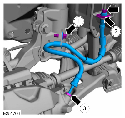
- Remove and discard the upper arm-to-subframe bolt.
-
Remove and discard the upper arm-to-wheel knuckle nut.
-
Using the special service tool disconnect the upper arm from wheel knuckle and remove the upper arm.
 |
Installation
-
To install, reverse the removal procedure.
-
NOTICE: Tighten the suspension bushing fasteners with the suspension loaded or with the weight of the vehicle resting on the wheels and tires, otherwise incorrect clamp load and bushing damage may occur.
NOTICE: Make sure that the ball joint ball does not rotate.
-
Install the new upper arm-to-subframe and press the upper arm to wheel knuckle.
-
Install the upper arm-to-wheel knuckle new nut.
Torque:
Stage 1: 177 lb.in (20 Nm)
Stage 2: 90°
-
Install the upper arm-to-subframe new bolt.
Torque:
Stage 1: 41 lb.ft (55 Nm)
Stage 2: 90°
-
Install the new upper arm-to-subframe and press the upper arm to wheel knuckle.
 |
-
Check and if necessary adjust rear toe.
Refer to: Rear Toe Adjustment - AWD (204-00 Suspension System - General Information, General Procedures).

 Removal and Installation - Rear Lower Arm
Special Tool(s) /
General Equipment
Transmission Jack
Removal
NOTICE:
Suspension fasteners are critical parts that affect the
performance of vital components and systems...
Other information:
Ford Ecosport 2014-2026 Service and Repair Manual: Removal and Installation - Generator - 2.0L Duratec-HE (129kW/175PS)
Removal NOTE: Removal steps in this procedure may contain installation details. With the vehicle in NEUTRAL, position it on a hoist. Refer to: Jacking and Lifting - Overview (100-02 Jacking and Lifting, Description and Operation)...
Ford Ecosport 2014-2026 Service and Repair Manual: Removal and Installation - Roof Rear Frame
Special Tool(s) / General Equipment Resistance Spotwelding Equipment Spot Weld Drill Bit Locking Pliers Materials Name Specification Seam SealerTA-2-B, 3M™ 08308, LORD Fusor® 803DTM - Removal NOTE: Factory welds may be substituted with resistance or metal inert gas (MIG) plug welds...
Categories
- Manuals Home
- 2nd Gen Ford Ecosport Service Manual (2014 - 2026)
- Removal and Installation - Evaporative Emission Canister Purge Valve
- Body and Paint
- Description and Operation - Evaporative Emissions - System Operation and Component Description
- Removal and Installation - Rear Bumper
- Diagnosis and Testing - Body Control Module (BCM)
Removal and Installation - Front Brake Flexible Hose
Removal
Remove the wheel and tire.Refer to: Wheel and Tire (204-04A Wheels and Tires, Removal and Installation).
Remove the brake flexible hose bracket bolt.
Disconnect the brake tube fitting and remove the brake hose clip.
Loosen the brake hose fitting and remove the brake flexible hose.