Ford Ecosport: Automatic Transmission - 6-Speed Automatic Transmission – 6F35 / Removal and Installation - Transmission
Special Tool(s) /
General Equipment
 |
303-F072
Support Bar, Engine |
 |
307-566
Retainer, Torque Converter
TKIT-2006C-FFMFLM
TKIT-2006C-LM
TKIT-2006C-ROW |
| Magnetic Socket |
| Transmission Jack |
Materials
| Name |
Specification |
Motorcraft® Multi-Purpose Grease Spray
XL-5-A |
ESB-M1C93-B
|
Motorcraft® Threadlock and Sealer
TA-25-B |
-
|
Motorcraft® Silicone Brake Caliper Grease and Dielectric Compound
XG-3-A |
ESA-M1C200-A
ESE-M1C171-A
|
Motorcraft® MERCON® LV Automatic Transmission Fluid
XT-10-QLVC |
WSS-M2C938-A
MERCON® LV,
|
Removal
All vehicles
-
With the vehicle in NEUTRAL, position it on a hoist.
Refer to: Jacking and Lifting - Overview (100-02 Jacking and Lifting, Description and Operation).
-
Remove the following items:
-
Refer to: Air Cleaner (303-12C Intake Air Distribution and Filtering -
2.0L Duratec-HE (129kW/175PS), Removal and Installation).
-
Refer to: Air Cleaner Outlet Pipe (303-12C Intake Air Distribution and
Filtering - 2.0L Duratec-HE (129kW/175PS), Removal and Installation).
-
Refer to: Battery Tray (414-01 Battery, Mounting and Cables, Removal and Installation).
-
Refer to: Cowl Panel (501-02 Front End Body Panels, Removal and Installation).
-
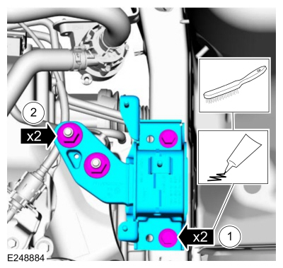
Disconnect the wiring harness retainers. Remove the bracket nuts and the battery tray bracket.
-
Disconnect the selector lever cable end from the
manual control lever. Remove the bracket bolts and position aside the
selector lever cable and bracket.
-
Disconnect the vent tube retainer.
-
Disconnect the wiring harness retainers.
-
Remove the front subframe.
Refer to: Front Subframe (502-00 Uni-Body, Subframe and Mounting System, Removal and Installation).
-
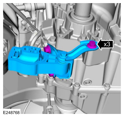
Remove the bolts, the roll restrictor and bracket.
-
Disconnect the transmission cooler lines.
-
Remove the nut and the ground cable.
-
Remove the starter motor.
Refer to: Starter Motor (303-06C Starting System - 2.0L Duratec-HE (129kW/175PS), Removal and Installation).
-
Remove the starter motor insulator.
-
Remove the bolts and the A/C compressor belt cover.
-
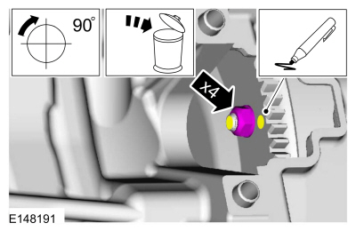
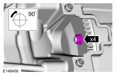
NOTICE:
Only rotate the engine in a clockwise direction or engine damage will occur.
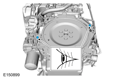
NOTE:
Index mark one stud and the flexplate for assembly reference.
Using a magnetic socket, remove and discard the torque converter nuts.
Use the General Equipment: Magnetic Socket
-
Disconnect the wiring harness retainers and the transmission electrical connector.
-
Disconnect the wiring harness retainer and the TSS sensor electrical connector.
-
Disconnect the transmission fluid auxiliary pump electrical connector.
-
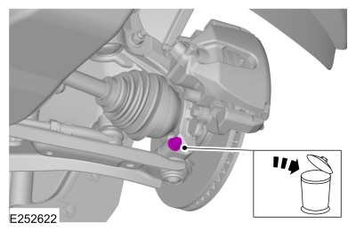
NOTE:
If transmission disassembly or installation of a
new transmission is necessary, drain the transmission fluid.
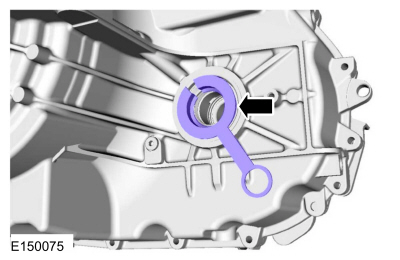
Remove the drain plug and drain the transmission. Install the drain plug.
Torque:
106 lb.in (12 Nm)
-
Remove the wheel and tire.
Refer to: Wheel and Tire (204-04A Wheels and Tires, Removal and Installation).
-
 WARNING:
Make sure that no load is placed on the brake hose.
WARNING:
Make sure that no load is placed on the brake hose.
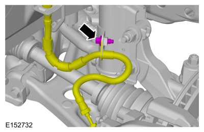
Remove the bolt and position aside the LH brake hose.
-
WARNING:
Make sure that the alignment line is not twisted.
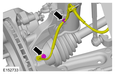
Remove the bolt, detach the retainer and position aside the LH front wheel speed sensor.
-
WARNING:
Make sure that a new bolt is installed.
NOTE:
Do not use a prying device or separator fork
between the ball joint and the wheel knuckle. Damage to the ball joint
or ball joint seal may result. Only use the pry bar by inserting it into
the lower arm body opening.
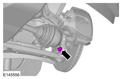
NOTE:
Use care when releasing the lower arm and wheel
knuckle into the resting position or damage to the ball joint seal may
occur.
Remove and discard the LH lower ball joint nut and bolt.
-
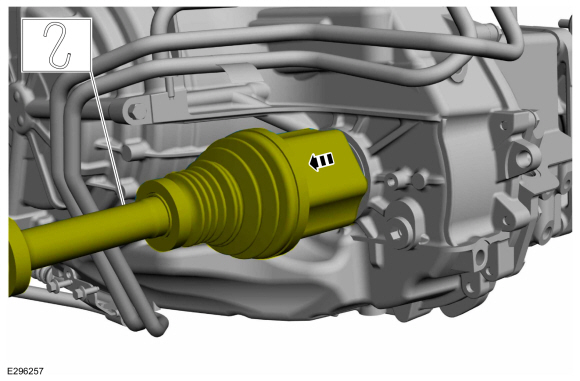
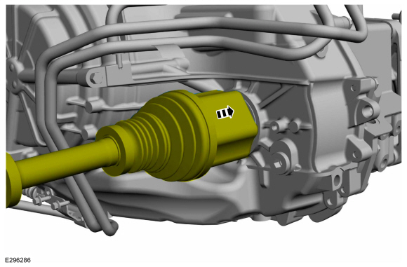
NOTE:
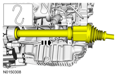
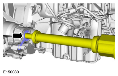
Do not pull on the halfshaft. Pull or pry on the inner CV housing only or damage may occur.
Position aside and support the LH halfshaft.
-
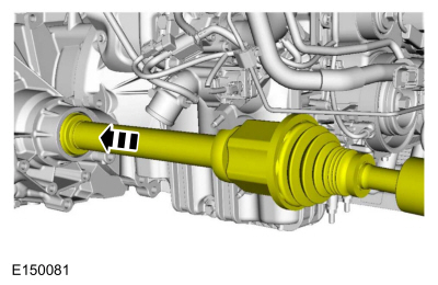
Remove and discard the halfshaft retaining circlip.
Vehicles with front wheel drive (FWD)
-
WARNING:
Make sure that no load is placed on the brake hose.
Remove the bolt and position aside the RH brake hose.
-
WARNING:
Make sure that the alignment line is not twisted.
Remove the bolt, detach the retainer and position aside the RH front wheel speed sensor.
-
WARNING:
Make sure that a new bolt is installed.
NOTE:
Do not use a prying device or separator fork
between the ball joint and the wheel knuckle. Damage to the ball joint
or ball joint seal may result. Only use the pry bar by inserting it into
the lower arm body opening.
NOTE:
Use care when releasing the lower arm and wheel
knuckle into the resting position or damage to the ball joint seal may
occur.
Remove and discard the RH lower ball joint nut and bolt.
-
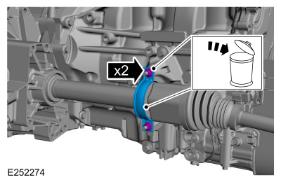
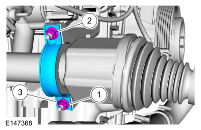
Remove and discard the halfshaft retaining strap and nuts.
-
NOTE:
Do not pull on the halfshaft or the CV joint will separate. Always pull on the intermediate shaft.
Position aside and support the RH halfshaft.
Vehicles with all wheel drive (AWD)
-
Remove the transfer case assembly.
Refer to: Transfer Case (308-07B Transfer Case - 6-Speed Automatic Transmission – 6F35, Removal).
All vehicles
-
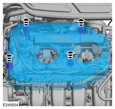
NOTICE:
Do not pull the engine appearance cover forward
or sideways to remove. Failure to press straight upward on the underside
of the cover at the attachment points may result in damage to the cover
or engine components.
-
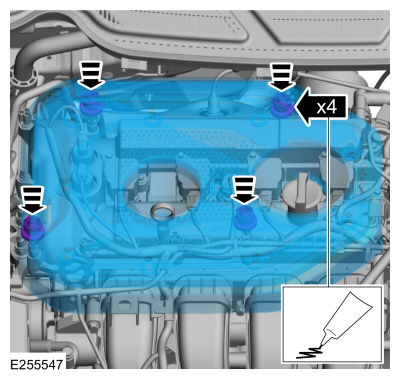
Place your hand under the engine appearance
cover at each grommet location and push straight up to release each
grommet from the studs.
-
After all of the grommets have been released
from the studs, remove the appearance cover from the engine.
-
Install the special tool and support the engine.
Use Special Service Tool: 303-F072
Support Bar, Engine.
-
Remove the upper transmission-to-engine bolts.
-
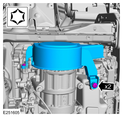
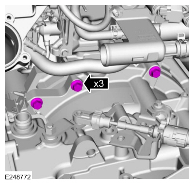
Remove the nuts, bolts and the transmission support insulator.
-
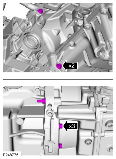
Remove the transmission-to-engine bolts.
-
NOTICE:
Secure the transmission to the transmission jack with a safety strap.
Support the transmission with a transmission jack.
Use the General Equipment: Transmission Jack
-
Remove the transmission-to-engine bolts.
-
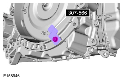
Separate the transmission from the engine, install the special tool and remove the transmission.
Use Special Service Tool: 307-566
Retainer, Torque Converter.
-
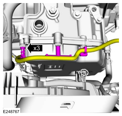
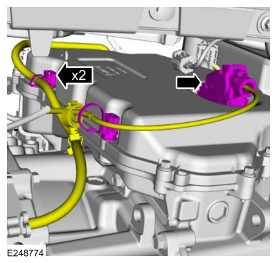
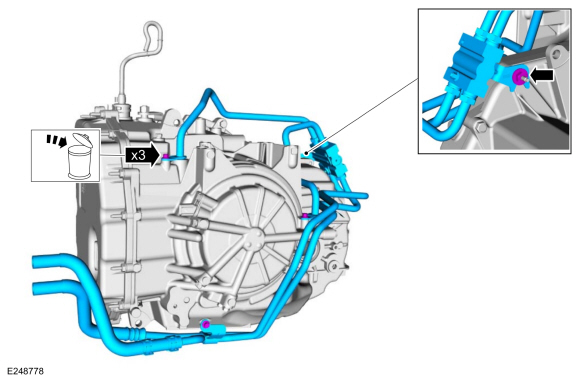
NOTE:
If transmission disassembly or installation of a
new transmission is necessary, remove the transmission mounted
transmission fluid cooler tubes.
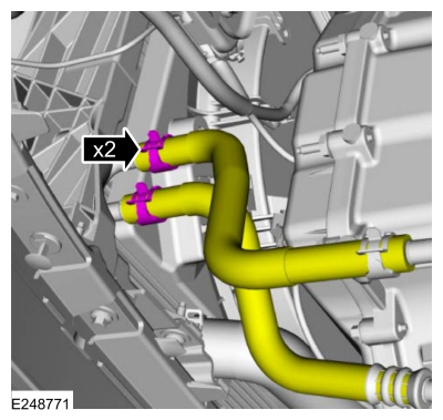
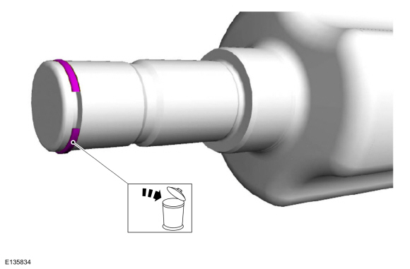
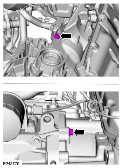
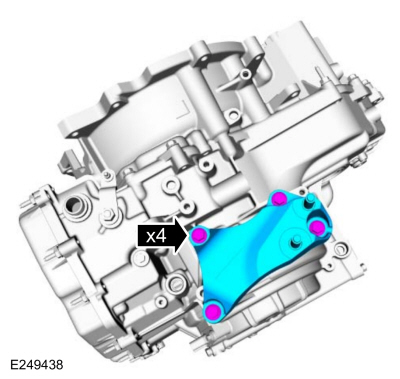
Remove and discard the transmission cooler tube
bolts. Remove the nut, bolt and the transmission mounted transmission
fluid cooler tubes.
-
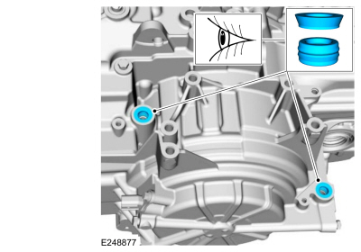
Inspect the transmission case to be sure that the
transmission fluid cooler tube seals and backing rings were removed with
the transmission fluid cooler tubes and are not stuck in the
transmission case. If the transmission fluid cooler tube seals or
backing rings are stuck in the transmission case, remove the seals and
backing rings.
-
NOTICE:
Failure to clean the transmission fluid cooler tubes can result in transmission failure.
If the transmission is to be overhauled or if
installing a new or re-manufactured transmission, carry out the
transmission fluid cooler backflushing and cleaning. Clean the
transmission-mounted transmission fluid cooler tubes by hand.
Refer to: Transmission Fluid Cooler - Backflushing and Cleaning
(307-02B Transmission Cooling - 6-Speed Automatic Transmission – 6F35,
General Procedures).
-
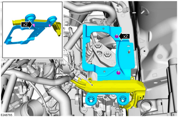
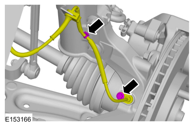
NOTE:
If transmission disassembly or installation of a
new transmission is necessary, remove the transmission support
insulator bracket.
Remove the transmission support insulator bracket.
-
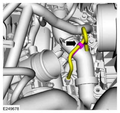
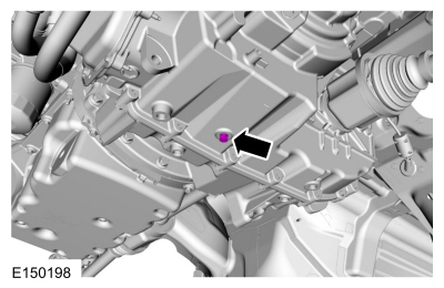
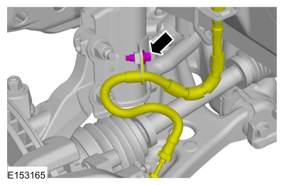
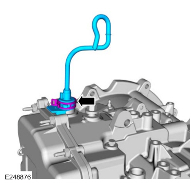
NOTE:
If transmission disassembly or installation of a new transmission is necessary, remove the vent tube.
Remove the vent tube.
-
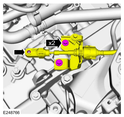
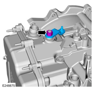
NOTE:
If transmission disassembly or installation of a new transmission is necessary, remove the manual lever.
Remove the nut and the manual lever.
-
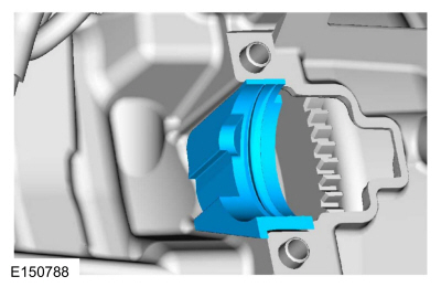
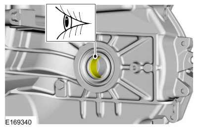
Inspect the transmission case bushing. If the
surface shows signs of excessive wear or damage, replace the
transmission case bushing.
Refer to: Transmission Case Bushing (307-01B Automatic Transmission -
6-Speed Automatic Transmission – 6F35, Removal and Installation).
-
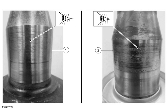
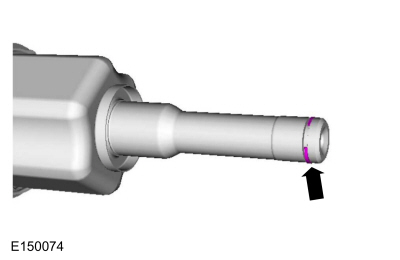
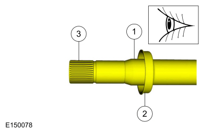
Inspect the LH halfshaft journal. If there is metal transfer on the journal, replace the LH halfshaft.
-
Halfshaft journal with normal wear.
-
Halfshaft journal with metal transfer.
-
Inspect the LH halfshaft hub for wear or damage and install a new halfshaft, if necessary.
-
Inspect the differential seal surface.
-
Inspect the halfshaft bushing surface. If this
surface is damaged, inspect the halfshaft bushing for damage.
-
Inspect the differential side gear splines.
Installation
All vehicles
-
Install the manual lever and the nut.
Torque:
18 lb.ft (24 Nm)
-
Install the vent tube.
-
Install the transmission support insulator bracket.
Torque:
46 lb.ft (62 Nm)
-
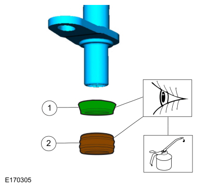
NOTE:
If removed, inspect the transmission mounted
transmission fluid cooler tube backing rings and seals for damage and
install new backing rings or seals if necessary.
-
Install the backing ring (7J324)
-
Lubricate and install the seal (7D285)
Material: Motorcraft® MERCON® LV Automatic Transmission Fluid
/ XT-10-QLVC
(WSS-M2C938-A)
(MERCON® LV, )
-
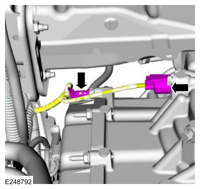
Install the transmission mounted transmission fluid cooler tubes, the new bolts and the nut.
Torque:
Bolts:
97 lb.in (11 Nm)
Nut:
80 lb.in (9 Nm)
-
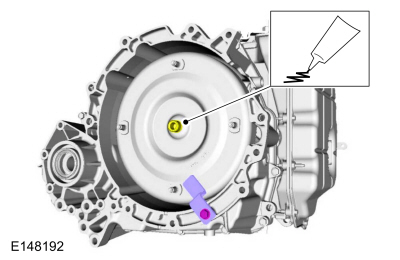
Lubricate the torque converter pilot hub with Multi-Purpose Grease.
Material: Motorcraft® Multi-Purpose Grease Spray
/ XL-5-A
(ESB-M1C93-B)
-
NOTICE:
If the transmission is not positioned on the dowel pins, damage to the transmission may occur.
If the dowel pins were pulled out of the engine
block during removal, install new dowel pins in the engine block.
-
NOTICE:
Secure the transmission to the transmission jack with a safety strap.
Support the transmission with a transmission jack.
Use the General Equipment: Transmission Jack
-
NOTE:
Align the torque converter index-mark made during removal.
Position the transmission behind the engine and remove the special tool.
Use Special Service Tool: 307-566
Retainer, Torque Converter.
-
Install the transmission-to-engine bolts.
Torque:
35 lb.ft (48 Nm)
-
Install the transmission-to-engine bolts.
Torque:
35 lb.ft (48 Nm)
-
NOTE:
Clean the bolts using a wire brush and apply Motorcraft® Threadlock and Sealer to the threads.
Install the transmission support insulator.
-
Install the transmission support insulator bolts.
Material: Motorcraft® Threadlock and Sealer
/ TA-25-B
Torque:
66 lb.ft (90 Nm)
-
Install the transmission support insulator nuts.
Torque:
103 lb.ft (140 Nm)
-
Install the upper transmission-to-engine bolts.
Torque:
35 lb.ft (48 Nm)
-
NOTE:
Lubricating the grommets with silicone grease
will aid in the installation of the engine appearance cover, and any
future removal and installation of the cover.
-
Lubricate each grommet with silicone grease.
Material: Motorcraft® Silicone Brake Caliper Grease and Dielectric Compound
/ XG-3-A
(ESA-M1C200-A)
(ESE-M1C171-A)
-
Position the engine appearance cover onto engine with the grommets aligned with the studs.
-
Press down on the engine appearance cover at
each grommet location to attach the grommets onto the studs.
-
\Connect the transmission fluid auxiliary pump electrical connector.
-
Connect the wiring harness retainer and the TSS sensor electrical connector.
-
Connect the wiring harness retainers and the transmission electrical connector.
-
NOTICE:
Only rotate the engine in a clockwise direction or engine damage will occur.
NOTE:
The torque converter nuts are accessed from the top of the vehicle.
Using a magnetic socket install the new torque converter nuts.
Use the General Equipment: Magnetic Socket
Torque:
30 lb.ft (40 Nm)
-
Install the starter insulator.
-
Install the A/C compressor belt cover and the bolts.
Torque:
18 lb.ft (25 Nm)
-
Install the starter motor.
Refer to: Starter Motor (303-06C Starting System - 2.0L Duratec-HE (129kW/175PS), Removal and Installation).
-
Install the ground cable and the nut.
Torque:
16 lb.ft (22 Nm)
-
Connect the transmission cooler lines.
-
Install the roll restrictor, bracket and the bolts.
Torque:
59 lb.ft (80 Nm)
-
Install the new inner halfshaft retaining circlip.
-
NOTE:
If the transmission has been replaced or overhauled, the halfshaft seals do not need to be replaced.
Install a new LH halfshaft seal.
Refer to: Halfshaft Seal LH (307-01B Automatic Transmission - 6-Speed Automatic Transmission – 6F35, Removal and Installation).
-
Install the seal protector.
-
NOTE:
Do not fully install the shaft at this time.
Using seal protector, install the LH halfshaft splines through the seal protector and remove the seal protector.
-
Install the LH halfshaft until the halfshaft retaining clip is fully seated.
-
NOTE:
Make sure that a new component is installed.
Insert the lower LH ball joint into the wheel knuckle and install a new bolt and nut.
Torque:
38 lb.ft (52 Nm)
-
WARNING:
Make sure that the alignment line is not twisted.
-
Position back the LH front wheel speed sensor and install the bolt.
Torque:
80 lb.in (9 Nm)
-
Attach the LH wheel speed sensor retainer.
-
WARNING:
Make sure that no load is placed on the brake hose.
Position the LH brake hose and install the bolt.
Torque:
18 lb.ft (25 Nm)
Vehicles with all wheel drive (AWD)
-
Install the transfer case assembly.
Refer to: Transfer Case (308-07B Transfer Case - 6-Speed Automatic Transmission – 6F35, Installation).
Vehicles with front wheel drive (FWD)
-
NOTE:
If the transmission has been replaced or overhauled, the halfshaft seals do not need to be replaced.
Install a new RH halfshaft seal.
Refer to: Halfshaft Seal RH - FWD (307-01B Automatic Transmission -
6-Speed Automatic Transmission – 6F35, Removal and Installation).
-
-
Inspect the RH halfshaft seal surface.
-
Inspect the dust shield.
-
Inspect the differential side gear splines.
-
Install the seal protector.
-
NOTE:
Remove the seal protector before completely installing the halfshaft.
Install the RH halfshaft through the seal protector.
-
Remove the seal protector and insert the RH halfshaft until the
intermediate shaft bearing is centered in the intermediate shaft
bracket.
-
Install the new halfshaft retaining strap and the new halfshaft retaining strap nuts.
Torque:
Stage 1:
44 lb.in (5 Nm)
Stage 2:
18 lb.ft (25 Nm)
Stage 3:
18 lb.ft (25 Nm)
-
NOTE:
Make sure that a new component is installed.
Insert the RH lower ball joint into the wheel knuckle and install a new bolt and nut.
Torque:
38 lb.ft (52 Nm)
-
WARNING:
Make sure that the alignment line is not twisted.
-
Position back the RH front wheel speed sensor and install the bolt.
Torque:
80 lb.in (9 Nm)
-
Attach the wheel speed sensor retainer.
-
WARNING:
Make sure that no load is placed on the brake hose.
Position the RH brake hose and install the bolt.
Torque:
18 lb.ft (25 Nm)
All vehicles
-
Install the front subframe.
Refer to: Front Subframe (502-00 Uni-Body, Subframe and Mounting System, Removal and Installation).
-
Connect the wiring harness retainers.
-
Connect the vent tube retainer.
-
Install the selector lever cable bracket and the bolts.
Torque:
18 lb.ft (25 Nm)
-
Install the battery tray bracket and the nuts. Connect the wiring harness retainers.
Torque:
18 lb.ft (25 Nm)
-
Install the battery tray.
Refer to: Battery Tray (414-01 Battery, Mounting and Cables, Removal and Installation).
-
Adjust the selector lever cable.
Refer to: Selector Lever Cable Adjustment - 6-Speed Automatic
Transmission – 6F35 (307-05 Automatic Transmission External Controls,
General Procedures).
-
Install the following items:
-
Refer to: Cowl Panel (501-02 Front End Body Panels, Removal and Installation).
-
Refer to: Air Cleaner Outlet Pipe (303-12C Intake Air Distribution and
Filtering - 2.0L Duratec-HE (129kW/175PS), Removal and Installation).
-
Refer to: Air Cleaner (303-12C Intake Air Distribution and Filtering -
2.0L Duratec-HE (129kW/175PS), Removal and Installation).
-
Fill the transmission with transmission fluid.
Refer to: Transmission Fluid Drain and Refill (307-01B Automatic
Transmission - 6-Speed Automatic Transmission – 6F35, General
Procedures).
-
If a new solenoid body is installed, the solenoid body strategy must be updated.
Refer to: Transmission Strategy Download (307-01B Automatic
Transmission - 6-Speed Automatic Transmission – 6F35, General
Procedures).
Auto-Start Stop
-
NOTE:
TFT must be greater than 38ºC (100ºF) for the PCM to command the pump on.
Using the scan tool verify the TFT is above 38ºC (100ºF).
-
If TFT is below 38ºC (100ºF), run engine at 3000 RPM until specified temperature is achieved (approximately 2-4 minutes).
-
Prime the Transmission Fluid Auxiliary Pump.
-
Key ON, Engine OFF.
-
Using the scan tool, command TRANS_PMP_CMD to
80% for 30 seconds. If the pump cannot be commanded on, verify TFT is above 38ºC (100ºF).
-
Clear DTCs.
-
Carry out a road test until there is a stop / start
event. If the restart is harsh, repeat the Transmission Fluid Pump prime
procedure.
-
Continue road test and evaluate each stop / start
event. Repeat prime procedure until three consecutive normal stop /
start events are achieved.
All vehicles
-
Using a scan tool, drive the vehicle until the
transmission is at normal operating temperature 85-93°C (185-200°F).
-
After completing the repairs perform the Misfire Monitor Neutral Profile Correction procedure.
-
If a new solenoid body is installed, complete the Adaptive Learning Drive Cycle.
Refer to: Adaptive Learning Drive Cycle (307-01A Automatic Transmission
- 6-Speed Automatic Transmission – 6F15, General Procedures).
-
Check the transmission fluid level.
Refer to: Transmission Fluid Level Check (307-01B Automatic
Transmission - 6-Speed Automatic Transmission – 6F35, General
Procedures).
Removal
To remove the LH halfshaft bushing, transmission disassembly is required.
Refer to: Transmission (307-01A Automatic Transmission - 6-Speed Automatic Transmission – 6F15, Overhaul)...
Other information:
Removal
NOTE:
Removal steps in this procedure may contain installation details.
NOTE:
The PMI process must begin with the current ABS module installed. If
the current ABS module does not respond to the diagnostic scan tool, the
tool may prompt for As-Built Data as part of the repair...
Special Tool(s) /
General Equipment
Brake Caliper Piston Retractor
Materials
Name
Specification
Motorcraft® DOT 4 LV High Performance Motor Vehicle Brake FluidPM-20
WSS-M6C65-A2
Multi-Purpose Grease
WSS-M12A4-A2
Removal
NOTE:
Removal steps in this procedure may contain installation details...


 Removal and Installation - Transmission Case Bushing