Ford Ecosport: Rear Suspension - FWD / Removal and Installation - Trailing Arm Bushing
Special Tool(s) / General Equipment
 |
308-095 Installer, Input Shaft Bearing |
 |
308-109 Socket, Guide Sleeve |
| Spring Compressor | |
| Transmission Jack | |
Removal
NOTICE: Suspension fasteners are critical parts that affect the performance of vital components and systems. Failure of these fasteners may result in major service expense. Use the same or equivalent parts if replacement is necessary. Do not use a replacement part of lesser quality or substitute design. Tighten fasteners as specified.
-
Remove the wheel and tire.
Refer to: Wheel and Tire (204-04A Wheels and Tires, Removal and Installation).
-
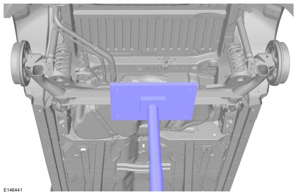
Support the transmission jack under the rear beam axle.
Use the General Equipment: Transmission Jack
 |
-
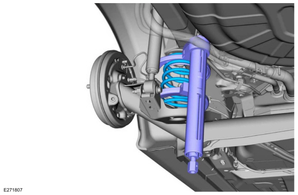
Using the special equipment, compress and remove the spring. WARNING:
Coil springs and strut assemblies are compressed
under extreme load. Always use a spring compressor for disassembly.
Follow procedure instructions carefully and make sure the spring
compressor has the correct spring plates or adapters. Failure to follow
these instructions may result in serious personal injury.
Use the General Equipment: Spring Compressor
 |
-
NOTE: Make sure that the jack is only placed underneath the rear axle tube and not under the rear damper bracket.
NOTE: Loosen the bolt completely and leave in place during the removal and installation.
-
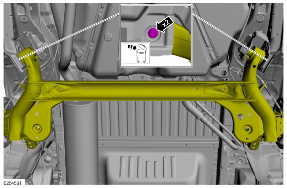
Remove the trailing arm bolts and discard.
-
Carefully lower the axle enough for the left hand trailing arm bolt to clear the fuel tank.
Use the General Equipment: Transmission Jack
-
Remove the trailing arm bolts and discard.
 |
-
NOTE: Note the position of the component before removal.
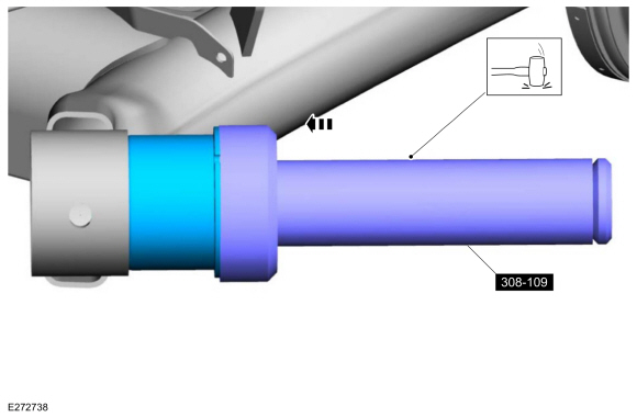
Remove the rear trailing arm bush.
Use Special Service Tool: 308-109 Socket, Guide Sleeve.
 |
Installation
-
NOTE: Make sure that the component is clean, free of foreign material and lubricant.
NOTE: Make sure that this component is installed to the noted removal position.
On both sides.
Install the new rear trailing arm bush..
Use Special Service Tool: 308-095 Installer, Input Shaft Bearing.
 |
-
 WARNING:
Coil springs and strut assemblies are compressed
under extreme load. Always use a spring compressor for disassembly.
Follow procedure instructions carefully and make sure the spring
compressor has the correct spring plates or adapters. Failure to follow
these instructions may result in serious personal injury.
-
Install the spring and remove the special service tool.
-
Remove the special service tool.
Use the General Equipment: Spring Compressor
-
Install the spring and remove the special service tool.
 |
-
NOTE: Make sure that your vehicle is on level ground.
On both sides.
-
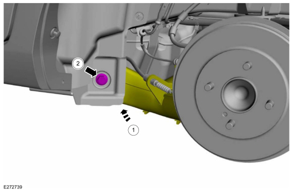
Position the trailing arm..
Use the General Equipment: Transmission Jack
-
NOTE: Only tighten the bolts finger tight at this stage.
Install the new rear trailing arm bushing bolt.
-
Position the trailing arm..
 |
-
Position aside the transmission jack.
Remove the General Equipment: Transmission Jack
 |
-
Install the wheel and tire.
Refer to: Wheel and Tire (204-04A Wheels and Tires, Removal and Installation).
-
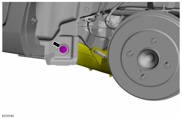
NOTICE: Tighten the suspension bushing fasteners with the suspension loaded or with the weight of the vehicle resting on the wheels and tires, otherwise incorrect clamp load and bushing damage may occur.
On both sides.
Tighten the trailing arm bolt.
Torque:
Stage 1: 59 lb.ft (80 Nm)
Stage 2: 120°
 |
 Removal and Installation - Beam Axle - Vehicles With: Rear Disc Brakes
Special Tool(s) /
General Equipment
204-167Compressor, Coil Spring
204-167-01Adapter for 204-167
Transmission Jack
Vehicle/Axle Stands
Interior Trim Remover
Removal
NOTICE:
Suspension fasteners are critical parts that affect the
performance of vital components and systems...
 Removal and Installation - Wheel Hub - Vehicles With: Rear Drum Brakes
Removal
NOTICE:
Suspension fasteners are critical parts that affect the
performance of vital components and systems. Failure of these fasteners
may result in major service expense...
Other information:
Ford Ecosport 2014-2026 Service and Repair Manual: General Procedures - Fuel System Pressure Check
Special Tool(s) / General Equipment 310-025-18Test Hose for 310-025 310-025-19ATest Hose for 310-025 GV2323 Connector Pressure Vacuum Transducer (C407) Pressure Vacuum Transducer (C219) Adapter Ford Diagnostic Equipment Connect WARNING: Before beginning any service procedure in this section, refer to Safety Warnings..
Ford Ecosport 2014-2026 Service and Repair Manual: Removal and Installation - Active Grille Shutter - 2.0L Duratec-HE (125kW/170PS) – MI4
Special Tool(s) / General Equipment Vehicle/Axle Stands Removal NOTE: Removal steps in this procedure may contain installation details. NOTE: Support the hood with a commercially available hood prop. Open the Hood. Remove the front bumper. Refer to: Front Bumper (501-19 Bumpers, Removal and Insta..

 WARNING:
Wear eye and ear protection when servicing a vehicle.
Failure to follow this instruction may result in serious personal
injury.