Ford Ecosport: Rear Suspension - FWD / Removal and Installation - Beam Axle - Vehicles With: Rear Disc Brakes
Special Tool(s) /
General Equipment
 |
204-167
Compressor, Coil Spring |
 |
204-167-01
Adapter for 204-167 |
| Transmission Jack |
| Vehicle/Axle Stands |
| Interior Trim Remover |
Removal
NOTICE:
Suspension fasteners are critical parts that affect the
performance of vital components and systems. Failure of these fasteners
may result in major service expense. Use the same or equivalent parts if
replacement is necessary. Do not use a replacement part of lesser
quality or substitute design. Tighten fasteners as specified.
NOTE:
Removal steps in this procedure may contain installation details.
-
Refer to: Brake and Clutch Systems Health and Safety Precautions (100-00 General Information, Description and Operation).
-
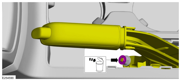
Apply the parking brake and remove the parking brake control lever boot.
Use the General Equipment: Interior Trim Remover
-
Remove and discard the lock washer.
-
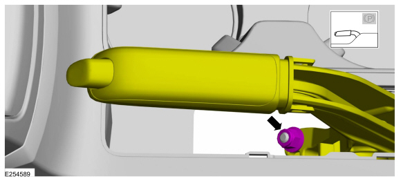
Release the parking brake cable tension and loosen the parking brake cable adjustment nut.
Loosen:
5 turn(s)
-
On both sides.
Remove the wheel and tire.
Refer to: Wheel and Tire (204-04A Wheels and Tires, Removal and Installation).
-
Remove the brake disc.
Refer to: Brake Disc (206-04 Rear Disc Brake, Removal and Installation).
-
On both sides.
Remove the rear wheel speed sensor retainers and position aside.
-
Position a transmission jack under the beam axle.
Use the General Equipment: Transmission Jack
-
On both sides.
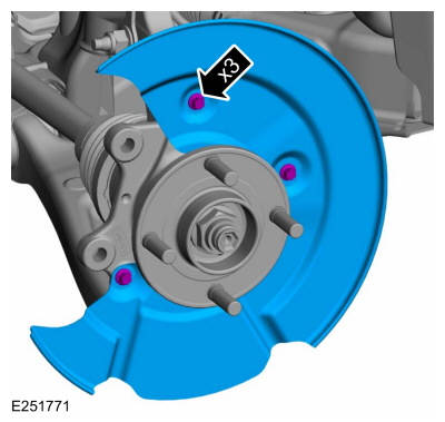
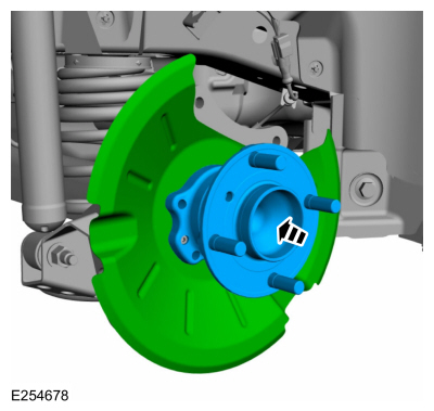
Remove and discard the wheel hub retainers.
-
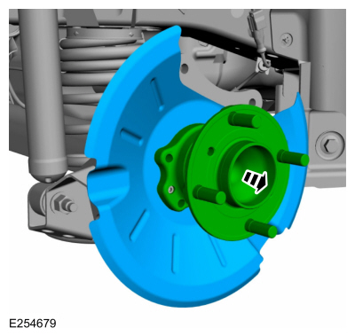
On both sides.
Remove the wheel hub and position aside the brake shield.
-
On both sides.
Detach the parking brake cable and the wheel speed sensor wiring from the bracket.
-
 WARNING:
Take extra care when handling the compressed spring.
WARNING:
Take extra care when handling the compressed spring.
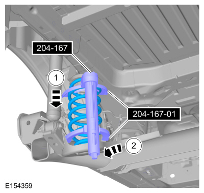
Using the special tool, compress and remove the spring.
Use Special Service Tool: 204-167
Compressor, Coil Spring.
, 204-167-01
Adapter for 204-167.
-
On both sides.
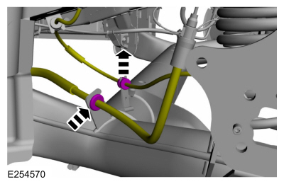
Support the rear suspension. Remove and discard rear shock absorber lower bolt and nut.
Use the General Equipment: Transmission Jack
-
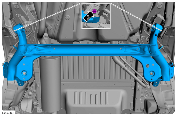
Remove and discard the beam axle bolts and remove the beam axle.
Installation
NOTICE:
Tighten the suspension bushing fasteners with the suspension
loaded or with the weight of the vehicle resting on the wheels and
tires, otherwise incorrect clamp load and bushing damage may occur.
-
-
Install the beam axle and the new beam axle bolts.
Use the General Equipment: Transmission Jack
Torque:
Stage 1:
59 lb.ft (80 Nm)
Stage 2:
120°
-
NOTE:
Only tighten the nuts finger tight at this stage.
On both sides.
Install the rear shock absorber and install the new rear shock absorber lower bolt and nut.
Use the General Equipment: Transmission Jack
-
WARNING:
Take extra care when handling the compressed spring.
Remove the following items:
-
-
Use Special Service Tool: 204-167
Compressor, Coil Spring.
, 204-167-01
Adapter for 204-167.
-
On both sides.
Attach the parking brake cable and the wheel speed sensor wiring to the bracket.
-
On both sides.
Install the brake backing plate, the wheel hub and the retainers.
-
NOTICE:
Make sure that new bolts are installed.
NOTE:
Only tighten the nuts finger tight at this stage.
On both sides.
Install the new wheel hub retainers.
-
On both sides.
Tighten the bolts in sequence in two stages.
Torque:
Stage 1:
18 lb.ft (25 Nm)
Stage 2:
50°
-
On both sides.
Install the wheel speed sensor bolt and fix the retainer.
Torque:
80 lb.in (9 Nm)
-
Install the brake disc.
Refer to: Brake Disc (206-04 Rear Disc Brake, Removal and Installation).
-
Check and if necessary adjust the parking brake cable.
Refer to: Parking Brake Cable Adjustment - Vehicles With: Rear Drum
Brakes (206-05 Parking Brake and Actuation, General Procedures).
-
On both sides.
Use the General Equipment: Vehicle/Axle Stands
-
On both sides.
Install the new rear shock absorber lower bolt and nut.
Use the General Equipment: Vehicle/Axle Stands
Torque:
85 lb.ft (115 Nm)
-
Bleed the brake system.
Refer to: Brake System Pressure Bleeding (206-00 Brake System - General Information, General Procedures).
Refer to: Brake System Pressure Bleeding (206-00 Brake System - General Information, General Procedures).
-
On both sides.
Install the wheel and tire.
Refer to: Wheel and Tire (204-04A Wheels and Tires, Removal and Installation).
Special Tool(s) /
General Equipment
204-167Compressor, Coil Spring
204-167-01Adapter for 204-167
Flat Headed Screw Driver
Transmission Jack
Vehicle/Axle Stands
Interior Trim Remover
Removal
NOTICE:
Suspension fasteners are critical parts that affect the
performance of vital components and systems...
Special Tool(s) /
General Equipment
308-095Installer, Input Shaft Bearing
308-109Socket, Guide Sleeve
Spring Compressor
Transmission Jack
Removal
NOTICE:
Suspension fasteners are critical parts that affect the
performance of vital components and systems...
Other information:
B0082:11, B0082:12, B0082:13, B0082:1A
Refer to Wiring Diagrams Cell 46 for schematic and connector information.
Normal Operation and Fault Conditions
The RCM continuously monitors the passenger seatbelt load limiter circuits for the following faults:
Resistance out of range
Unexpected voltage
Short to ground
Faulted passenger seatbelt load limite..
Intermediate (2, 6) Clutch Exploded View
Item
Description
1
Transmission case
2
Intermediate clutch piston
3
Intermediate clutch piston return spring
4
Intermediate clutch piston return spring snap ring
5
Intermediate clutch ..


 Removal and Installation - Beam Axle - Vehicles With: Rear Drum Brakes
 Removal and Installation - Trailing Arm Bushing