Ford Ecosport: Engine - 2.0L Duratec-HE (129kW/175PS) / Removal and Installation - Valve Cover
Special Tool(s) /
General Equipment
 |
205-153
(T80T-4000-W)
Handle |
 |
303-1247
VCT Spark Plug Tube Seal Remover and Installer
TKIT-2006UF-FLM
TKIT-2006UF-ROW |
| Plastic Scraper |
Materials
| Name |
Specification |
Motorcraft® Silicone Gasket and Sealant
TA-30 |
WSE-M4G323-A4
|
Removal
NOTICE:
During engine repair procedures, cleanliness is extremely
important. Any foreign material, including any material created while
cleaning gasket surfaces, that enters the oil passages, coolant passages
or the oil pan can cause engine failure.
-
Release the fuel system pressure.
Refer to: Fuel System Pressure Release (310-00C Fuel System - General
Information - 2.0L Duratec-HE (129kW/175PS), General Procedures).
-
Disconnect the battery ground.
Refer to: Battery Disconnect and Connect (414-01 Battery, Mounting and Cables, General Procedures).
-
Remove the ignition coil-on-plugs.
Refer to: Ignition Coil-On-Plug (303-07C Engine Ignition - 2.0L Duratec-HE (129kW/175PS), Removal and Installation).
-
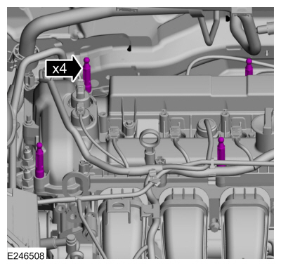
Remove the engine appearance cover bolts.
-
Detach the degas coolant hose retainer from the valve cover stud bolt.
-
-
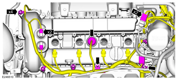
Disconnect the wiring harness electrical connectors.
-
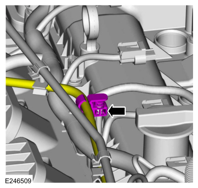
Detach the CHT wiring harness cover plug.
-
Detach the wiring harness retainers and position the wiring harness aside.
-
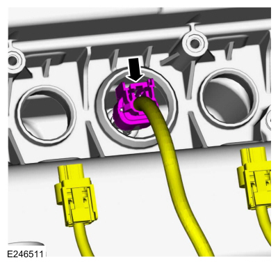
Disconnect the CHT wiring harness electrical connector.
-
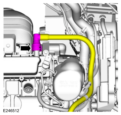
Disconnect the crankcase vent tube quick release coupling and position aside.
Refer to: Quick Release Coupling (310-00 Fuel System -
General Information - 2.0L Duratec-HE (129kW/175PS), 2.0L Duratec-HE
(125kW/170PS) – MI4, 2.0L Duratec-HE Flex Fuel (129kW/175PS))
.
-
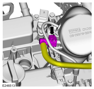
Disconnect the fuel tube quick release coupling and position aside.
Refer to: Quick Release Coupling (310-00 Fuel System -
General Information - 2.0L Duratec-HE (129kW/175PS), 2.0L Duratec-HE
(125kW/170PS) – MI4, 2.0L Duratec-HE Flex Fuel (129kW/175PS))
.
-
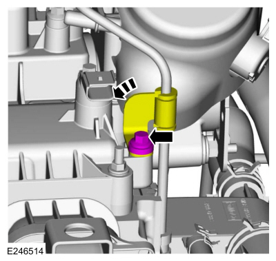
Remove the bolt and position the fuel tube clamp aside.
-
Remove the oil level indicator.
-
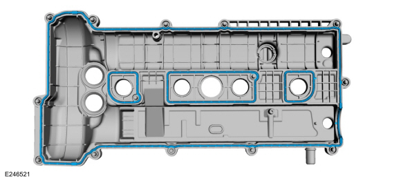
Loosen the fasteners and remove the valve cover.
-
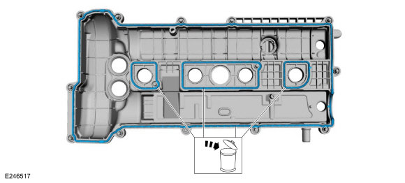
Remove and discard the valve cover gaskets.
-
NOTICE:
Do not use metal scrapers, wire brushes, power
abrasive discs or other abrasive means to clean the sealing surfaces.
These tools cause scratches and gouges which make leak paths.
Clean the valve cover.
-
NOTICE:
Do not use metal scrapers, wire brushes, power
abrasive discs or other abrasive means to clean the sealing surfaces.
These tools cause scratches and gouges which make leak paths.
Make sure that the mating faces are clean and free of foreign material.
Use the General Equipment: Plastic Scraper
-
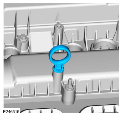
NOTE:
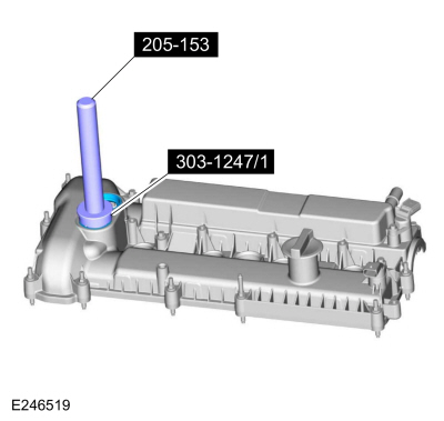
The Variable Camshaft Timing (VCT) solenoid seals should only be replaced if they are damaged.
Inspect the VCT oil control solenoid seals for damaged. If damaged,
using the special tools, remove the VCT oil control solenoid seals and
discard.
Use Special Service Tool: 205-153
(T80T-4000-W)
Handle.
, 303-1247
VCT Spark Plug Tube Seal Remover and Installer.
Installation
-
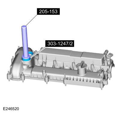
NOTE:
Installation of new seals is only required if damaged seals were removed during removal of the valve cover.
Using the special tools, install the VCT oil control solenoid seals.
Use Special Service Tool: 205-153
(T80T-4000-W)
Handle.
, 303-1247
VCT Spark Plug Tube Seal Remover and Installer.
-
Install new valve cover gaskets.
-
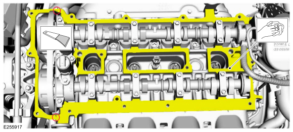
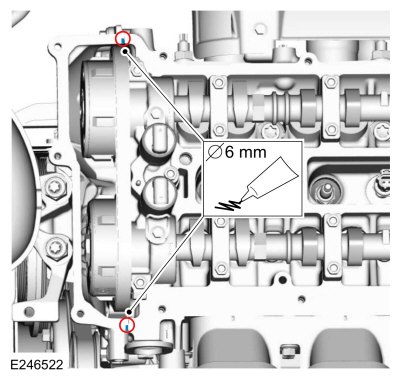
NOTE:
The valve cover must be secured within 10 minutes
of silicone gasket application. If the valve cover is not secured within
10 minutes, the sealant must be removed and the sealing area cleaned.
Apply a 6 mm bead of silicone sealant as shown.
Material: Motorcraft® Silicone Gasket and Sealant
/ TA-30
(WSE-M4G323-A4)
-
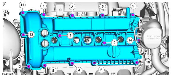
Install the valve cover and tighten the bolts in sequence shown.
Torque:
89 lb.in (10 Nm)
-
Install the oil level indicator.
-
Position back the fuel tube clamp and install the bolt.
Torque:
89 lb.in (10 Nm)
-
Position and connect the fuel tube quick release coupling.
Refer to: Quick Release Coupling (310-00 Fuel System -
General Information - 2.0L Duratec-HE (129kW/175PS), 2.0L Duratec-HE
(125kW/170PS) – MI4, 2.0L Duratec-HE Flex Fuel (129kW/175PS))
.
-
Position and connect the crankcase vent tube quick release coupling.
Refer to: Quick Release Coupling (310-00 Fuel System -
General Information - 2.0L Duratec-HE (129kW/175PS), 2.0L Duratec-HE
(125kW/170PS) – MI4, 2.0L Duratec-HE Flex Fuel (129kW/175PS))
.
-
Connect the CHT wiring harness electrical connector.
-
-
Position and attach the wiring harness retainers.
-
Attach the CHT wiring harness cover plug.
-
Connect the wiring harness electrical connectors.
-
Attach the degas coolant hose retainer to the valve cover stud bolt.
-
Install the engine appearance cover bolts.
Torque:
27 lb.in (3 Nm)
-
Install the ignition coil-on-plugs.
Refer to: Ignition Coil-On-Plug (303-07C Engine Ignition - 2.0L Duratec-HE (129kW/175PS), Removal and Installation).
-
Connect the battery ground.
Refer to: Battery Disconnect and Connect (414-01 Battery, Mounting and Cables, General Procedures).
Special Tool(s) /
General Equipment
303-1565Alignment Tool, CamshaftTKIT-2010C-FLM
Removal
NOTICE:
Do not loosen or remove the crankshaft pulley bolt without
first installing the special tools as instructed in this procedure...
Removal
Remove the camshafts.
Refer to: Camshaft (303-01C Engine - 2.0L Duratec-HE (129kW/175PS), Removal and Installation).
NOTE:
If the camshafts and valve tappets are to be
reused, mark the location of the valve tappets to make sure they are
assembled in their original positions...
Other information:
System Operation
Engine coolant flows primarily from the engine to the radiator circuit
and back to the coolant pump. Coolant is sent from the coolant pump
through the engine block and cylinder head. A separate circuit from the
engine also feeds the heater core with coolant...
Inspection
NOTE:
Dropped spark plugs should always be discarded.
Unfired
An unfired spark plug should appear very clean
with a pure nickel finish to the threads and ground strap. The center
electrode ceramic insulator surface is often a matte or dull finish and
pure white in color...


 Removal and Installation - Timing Chain
 Removal and Installation - Valve Tappets