Ford Ecosport: Rear Suspension - AWD / Removal and Installation - Rear Shock Absorber
Special Tool(s) / General Equipment
| Transmission Jack |
Removal
NOTICE: Suspension fasteners are critical parts that affect the performance of vital components and systems. Failure of these fasteners may result in major service expense. Use the same or equivalent parts if replacement is necessary. Do not use a replacement part of lesser quality or substitute design. Tighten fasteners as specified.
NOTE: Removal steps in this procedure may contain installation details.
-
Remove the wheel and tire.
Refer to: Wheel and Tire (204-04A Wheels and Tires, Removal and Installation).
-
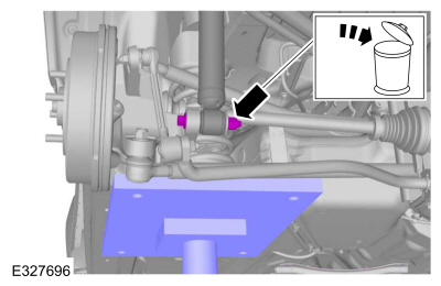
Remove and discard rear shock absorber lower bolt and nut.
Use the General Equipment: Transmission Jack
 |
-
-
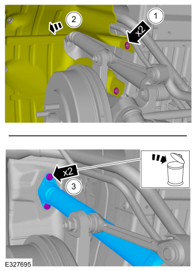
Remove the retainers.
-
Position aside the fender splash shield.
-
Remove and discard the upper bolts and remove the rear shock absorber.
-
Remove the retainers.
 |
Installation
-
-
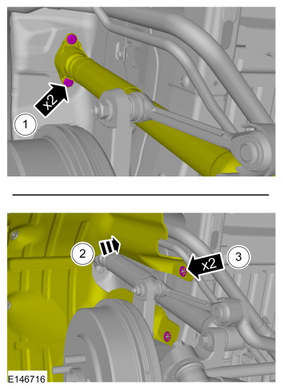
Install the rear shock absorber and install the rear shock absorber upper bolts.
Torque: 22 lb.ft (30 Nm)
-
Position the fender splash shield.
-
Fix the retainer.
-
Install the rear shock absorber and install the rear shock absorber upper bolts.
 |
-
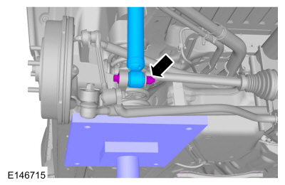
NOTE: Only tighten the nuts finger tight at this stage.
Install the new rear shock absorber lower bolt and nut.
Use the General Equipment: Transmission Jack
 |
-
NOTICE: Tighten the suspension bushing fasteners with the suspension loaded or with the weight of the vehicle resting on the wheels and tires, otherwise incorrect clamp load and bushing damage may occur.
Tighten the rear shock absorber lower bolt and nut.
Use the General Equipment: Transmission Jack
Torque: 76 lb.ft (103 Nm)
 |
-
Install the wheel and tire.
Refer to: Wheel and Tire (204-04A Wheels and Tires, Removal and Installation).
 Removal and Installation - Spring
Special Tool(s) /
General Equipment
Spring Compressor
Vise
Removal
NOTICE:
Suspension fasteners are critical parts that affect the
performance of vital components and systems...
 Removal and Installation - Wheel Knuckle Bushing
Special Tool(s) /
General Equipment
Hydraulic Press
Removal
NOTE:
Removal steps in this procedure may contain installation details...
Other information:
Ford Ecosport 2014-2025 Service and Repair Manual: Removal and Installation - Intake Manifold
Materials Name Specification Motorcraft® Silicone Brake Caliper Grease and Dielectric CompoundXG-3-A ESA-M1C200-AESE-M1C171-A Removal With the vehicle in NEUTRAL, position it on a hoist. Refer to: Jacking and Lifting - Overview (100-02 Jacking and Lifting, Description and Operation)...
Ford Ecosport 2014-2025 Service and Repair Manual: General Procedures - Compression and Cylinder Leakage Test
Make sure the oil in the crankcase is of the correct viscosity and at the correct level and that the battery is correctly charged. Operate the vehicle until the engine is at normal operating temperature. Turn the ignition switch to the OFF position...
Categories
- Manuals Home
- 2nd Gen Ford Ecosport Service Manual (2014 - 2025)
- Removal and Installation - Catalytic Converter
- Removal and Installation - Body Control Module (BCM)
- Description and Operation - Evaporative Emissions - System Operation and Component Description
- Engine
- Body and Paint
Removal and Installation - Rear Halfshaft Seal
Special Tool(s) / General Equipment
 205-153
(T80T-4000-W)
205-153
(T80T-4000-W)
Handle
 205-990
Installer, Axle Seal
TKIT-2012A-FL
TKIT-2012A-ROW