Ford Ecosport: Bumpers / Removal and Installation - Rear Bumper Cover
Ford Ecosport 2014-2025 Service and Repair Manual / Body and Paint / Bumpers / Removal and Installation - Rear Bumper Cover
Special Tool(s) / General Equipment
| Long Nose Pliers |
Removal
NOTE: Removal steps in this procedure may contain installation details.
-
Remove the rear wheel and tire assemblies.
Refer to: Wheel and Tire (204-04A Wheels and Tires, Removal and Installation).
-
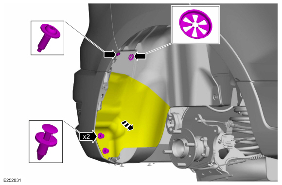
On both sides.
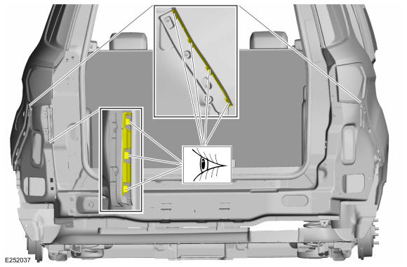
Remove the pin-type retainers, the clip, the screw and position the wheel liner aside.
Torque: 15 lb.in (1.7 Nm)
 |
-
On both sides.
Remove the screws.
Torque: 15 lb.in (1.7 Nm)
 |
-
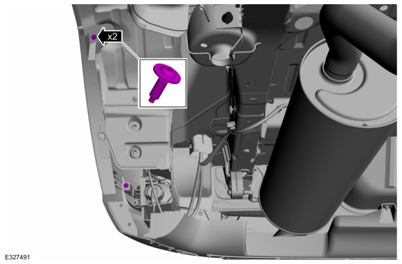
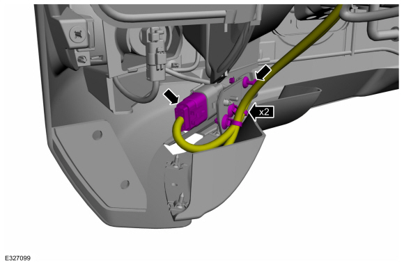
NOTE: RH side only.
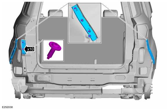
Disconnect the rear bumper harness electrical connector, detach the wiring harness retainers and remove the push pin.
 |
-
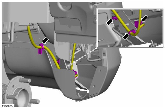
NOTE: LH side only.
Disconnect the rear bumper harness electrical connector, detach the wiring harness retainers and remove the push pin.
 |
-
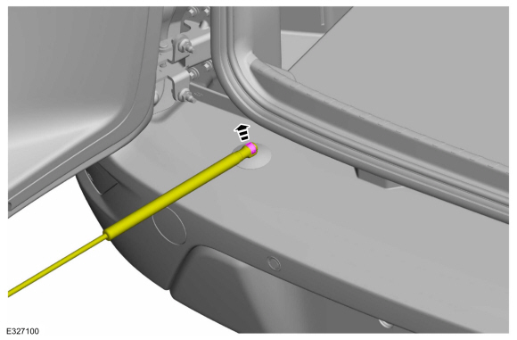
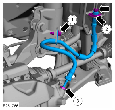
Using the pliers squeeze the clips and position the strut aside.
Use the General Equipment: Long Nose Pliers
 |
-
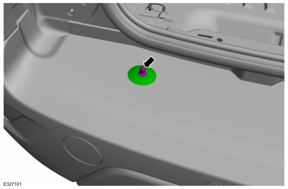
Remove the stud and washer.
 |
-
-
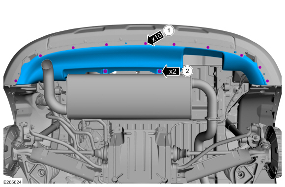
Remove the screws.
Torque: 13 lb.in (1.5 Nm)
-
Remove the clips and the rear air deflector.
Torque: 19 lb.in (2.2 Nm)
-
Remove the screws.
 |
-
Remove the pushpins, release the tabs and remove the bumper cover.
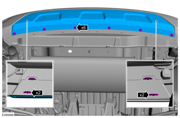 |
-
With the help of an assistant.
Remove the screws and the rear bumper cover.
Torque:
1.: 13 lb.in (1.5 Nm)
2.: 53 lb.in (6 Nm)
 |
-
Inspect the bumper reinforcements for damage to the bumper cover gripping surfaces.
 |
-
If required.
Remove the screws and the damaged bracket.
Torque: 13 lb.in (1.5 Nm)
 |
Installation
-
To install, reverse the removal procedure.
-
If replacing the rear bumper cover.
Carry out the azimuth and elevation system checks.
Refer to: Azimuth System Check (413-13A Parking Aid, General Procedures).
Refer to: Elevation System Check (413-13A Parking Aid, General Procedures).
-
If any sensor fails the check, diagnose the sensor fault.
Refer to: Parking Aid (413-13A Parking Aid, Diagnosis and Testing).
 Removal and Installation - Rear Bumper
Removal
NOTE:
Removal steps in this procedure may contain installation details.
Remove the rear bumper cover.
Refer to: Rear Bumper Cover (501-19 Bumpers, Removal and Installation)...
 Disassembly and Assembly - Front Bumper Cover
Special Tool(s) /
General Equipment
Hot Air Gun
DISASSEMBLY
Remove the front bumper cover.
Refer to: Front Bumper Cover (501-19 Bumpers, Removal and Installation)...
Other information:
Ford Ecosport 2014-2025 Service and Repair Manual: General Procedures - Factory Mode Deactivation
Deactivation NOTE: During vehicle build, some modules, such as the IPC and BCM are set in factory mode. Factory mode reduces the drain on the battery during longer periods where the vehicle is not used. While in the factory mode, various systems may be altered or disabled and the IPC displays FACTORY MODE CONTACT DEALER in the message center...
Ford Ecosport 2014-2025 Service and Repair Manual: Diagnosis and Testing - Turn Signal and Hazard Lamps
DTC Chart: BCM Diagnostics in this manual assume a certain skill level and knowledge of Ford-specific diagnostic practices. REFER to: Diagnostic Methods (100-00 General Information, Description and Operation). BCM DTC Chart DTC Description Action B123A:11 Left Front Tu..
Categories
- Manuals Home
- 2nd Gen Ford Ecosport Service Manual (2014 - 2025)
- Removal and Installation - Fuel Pump and Sender Unit
- Service Information
- Removal and Installation - Front Seat
- Engine
- Removal and Installation - Starter Motor
Removal and Installation - Front Brake Flexible Hose
Removal
Remove the wheel and tire.Refer to: Wheel and Tire (204-04A Wheels and Tires, Removal and Installation).
Remove the brake flexible hose bracket bolt.
Disconnect the brake tube fitting and remove the brake hose clip.
Loosen the brake hose fitting and remove the brake flexible hose.
Copyright © 2025 www.foecosport2.com