Ford Ecosport: Supplemental Restraint System / Removal and Installation - Occupant Classification System (OCS) Sensor - Vehicles With: Rear Seat Side Airbag
Removal
 WARNING:
The following procedure prescribes critical repair steps
required for correct restraint system operation during a crash. Follow
all notes and steps carefully. Failure to follow step instructions may
result in incorrect operation of the restraint system and increases the
risk of serious personal injury or death in a crash.
WARNING:
The following procedure prescribes critical repair steps
required for correct restraint system operation during a crash. Follow
all notes and steps carefully. Failure to follow step instructions may
result in incorrect operation of the restraint system and increases the
risk of serious personal injury or death in a crash.
NOTICE: To prevent system failure, carry out the OCS reset when a front passenger seat cushion is disassembled, a new trim cover is installed or an OCS service kit is installed. Use a scan tool to carry out the OCS reset command.
NOTICE: The cushion heater mat on a front outboard passenger seat is not serviced separately. If a new cushion heater mat is needed on the front passenger seat, install an OCS service kit equipped with a heater mat. Failure to follow this instruction may result in incorrect operation of the OCS .
NOTE: OCS components (seat cushion foam pad, bladder with OCSM ) are calibrated to each other and are serviced as an assembly. The OCS components are not to be installed separately. If a new OCS , OCS component or seat cushion foam pad are needed, a new OCS service kit (seat cushion foam pad, bladder with OCSM ) must be installed as an assembly.
NOTE: Removal steps in this procedure may contain installation details.
-
Refer to: Pyrotechnic Device Health and Safety Precautions (100-00 General Information, Description and Operation).
WARNING:
Before beginning any service procedure in this
manual, refer to health and safety warnings in section 100-00 General
Information. Failure to follow this instruction may result in serious
personal injury.
-
Remove the front passenger seat.
Refer to: Front Seat (501-10A Front Seats, Removal and Installation).
-
-
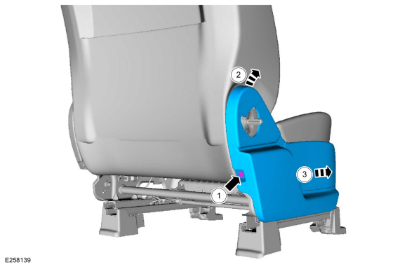
Remove the clip and the recline handle.
-
Release the locking tab and remove the height adjust handle.
-
Remove the clip and the recline handle.
 |
-
-
Remove the screw.
-
Lift the rear of the side shield up and out.
-
Slide forward and remove the side shield.
-
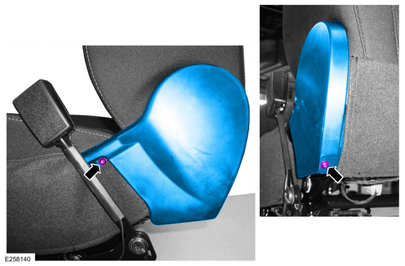
Remove the screw.
 |
-
Remove the screws and the recliner cover.
 |
-
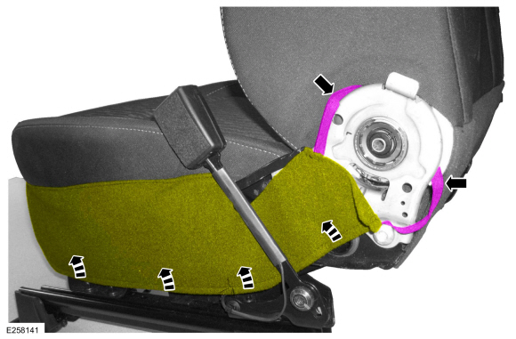
Release the strap and position the cushion cover up and over the seatbelt buckle.
 |
-
-
If equipped with heated seat.
Detach the electrical connector retainers.
-
If equipped with heated seat.
Disconnect the cushion heater mat electrical connector.
-
If equipped with heated seat.
 |
-
-
Detach the backrest cover straps.
-
Position the backrest cover up.
-
Detach the backrest cover straps.
 |
-
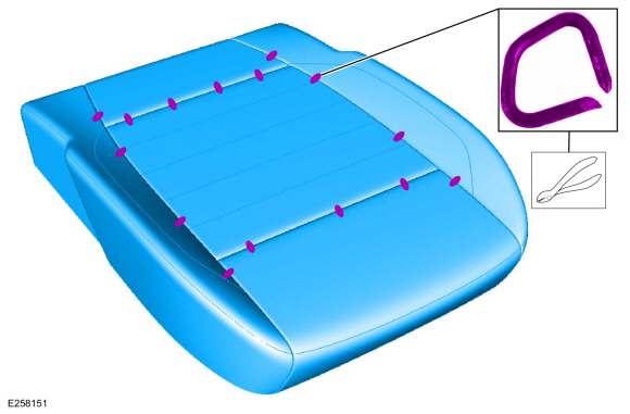
Detach the cushion cover rear J-clips.
 |
-
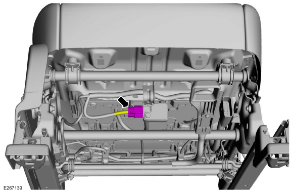
Disconnect the OCS sensor.
 |
-
-
On both sides.
Detach the cushion cover J-clips.
-
Detach the cushion cover J-clip.
-
On both sides.
 |
-
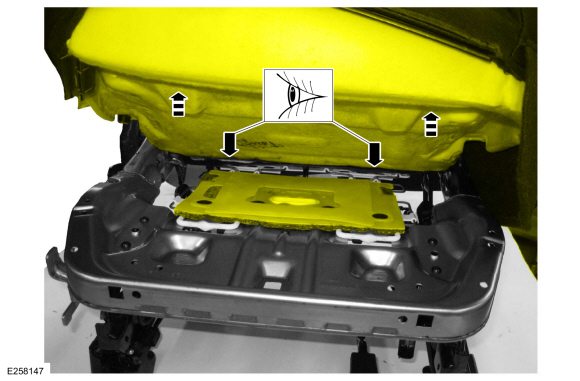
NOTE: When equipped with an OCS service kit, the OCS is adhered to the bottom of the front seat cushion foam. This requires the cushion cover, foam and OCS to be positioned aside as an assembly.
Lift the cushion foam. If the cushion foam and OCS are adhered together, then the OCS is a service kit. If nothing is adhered together, then the OCS is OE (original equipment).
 |
-
If equipped with an OE OCS .
Remove the cushion foam and cover as an assembly.
 |
-
NOTE: Typical OE OCS shown, service kit similar.
-
Remove the OCS sensor bracket screw.
Torque: 44 lb.in (5 Nm)
-
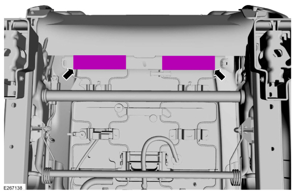
Remove the OCS pin-type retainers.
-
Remove the OCS sensor bracket screw.
 |
-
NOTE: For correct installation, note the location of the OCS hose and heater mat pigtail (if equipped) as it passes through the seat springs.
Route out the OCS hose, sensor, sensor bracket and heated seat cushion mat wiring pigtail (if equipped) from between the seat cushion support wires and remove the OCS .
 |
-
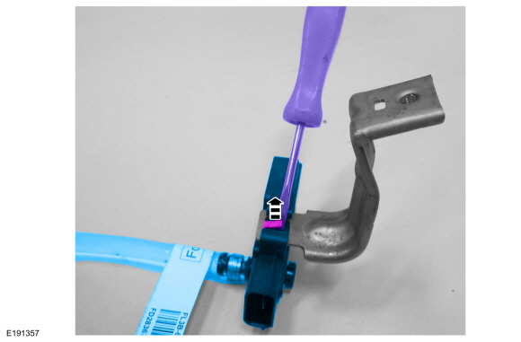
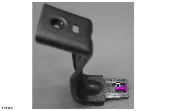
NOTE: This step is only necessary when installing a new OCS .
NOTE: Follow the unique instructions or graphic for this step in the installation.
Bend the tab up and slide the OCS sensor off the bracket.
 |
-
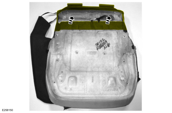
NOTE: This step is only necessary when installing a new OCS .
Position the rear portion of the seat cushion cover from the foam.
 |
-
NOTE: This step is only necessary when installing a new OCS .
Invert the cushion cover, remove the hog rings and the cushion cover.
 |
Installation
-
NOTICE: Inspect the OCS bladder, seat cushion pan and support assembly for any foreign objects before installing the OCS to the seat cushion pan. Remove any foreign objects. Failure to follow these instructions may result in incorrect operation of the OCS and may cause system failure.
NOTICE: Do not trap the pressure sensor hose incorrectly over the seat's suspension or spring. Route the hose so that it lays in a natural bend, and is not twisted due to being forced into an unnatural position. Failure to follow these instructions may result in component damage and/or system failure.
To install, reverse the removal procedure.
-
Bend the OCS sensor bracket tab back.
 |
-
Install the front passenger seat. Do not prove out the SRS at this time.
Refer to: Front Seat (501-10A Front Seats, Removal and Installation).
-
WARNING:
Occupant Classification System (OCS) parts are
calibrated as an assembly and must only be replaced in the configuration
they are sold. Never separate parts of an assembly. Failure to follow
this instruction may result in incorrect operation of the OCS and
increases the risk of serious personal injury or death in a crash.
WARNING:
Make sure the front passenger seat repair is
complete, the seat and all attached components (head restraint, seat
side shield, etc.) are correctly assembled, and the seat is correctly
installed to the vehicle before using System Reset to rezero the seat
weight. Failure to follow these instructions may result in incorrect
operation of the occupant classification system (OCS) and increases the
risk of serious personal injury or death in a crash.
NOTICE: To prevent system failure, take the following precautions before carrying out the OCS reset.
- Make sure the voltage to the OCSM is greater than 8 volts and less than 18 volts.
- Make sure the OCS is not below 6º C (42.8º F) or above 36º C (96.7º F) when initiating the OCS reset process. If the vehicle has been exposed to extreme cold or hot temperatures, the vehicle must be exposed and kept at a temperature between 6º C (42.8º F) to 36º C (96.7º F) for a minimum of 30 minutes.
- Make sure nothing is present on the passenger seat before and during the OCS reset process.
- Prior to carrying out the OCS reset, make sure a minimum of 8 seconds has elapsed after cycling the ignition switch on.
-
If the first system reset attempt was successful, proceed to prove out the SRS .
-
If the first system reset attempt was not successful, carry out a thorough visual inspection of the OCS
connector and wiring for damage, pressure sensor hose for kinks and or
damage, and seat-related wiring harness and body wiring harness
terminals and connectors for damage. Repair any concerns found and
proceed to the next step.
-
Carry out a second OCS reset. Cycle the ignition switch after the OCS
reset. If the second attempt is unsuccessful, install a new OCS service
kit.
-
Prove out the SRS
. Verify all airbags are installed and connected and the ignition is
OFF. Wait 10 seconds then turn the ignition ON and monitor the airbag
warning indicator. The airbag warning indicator illuminates continuously
for approximately 6 seconds and turns off. Continue to monitor the
airbag warning indicator for approximately 30 seconds, as this is the
time required for the RCM to complete testing of the SRS .
-
If a SRS
fault is present, the airbag warning indicator either fails to light,
remains lit continuously or flashes. The flashing may not occur until
approximately 30 seconds after the ignition has been turned from OFF to
ON. If this occurs, diagnose and repair any SRS faults before proceeding with other repairs.
-
If, after the ignition has been turned on for 30
seconds, the airbag warning indicator remains unlit with no chime or SRS
message displayed in the message center, no SRS fault is present.
-
If the airbag warning indicator is inoperative and a SRS
fault exists, a chime sounds in a pattern of 5 sets of 5 beeps or a
message displays in the message center. If this occurs, diagnose and
repair the airbag warning indicator and any SRS faults before proceeding with other repairs.
-
If a SRS
fault is present, the airbag warning indicator either fails to light,
remains lit continuously or flashes. The flashing may not occur until
approximately 30 seconds after the ignition has been turned from OFF to
ON. If this occurs, diagnose and repair any SRS faults before proceeding with other repairs.
-
Using a scan tool, clear all Continuous Memory Diagnostic Trouble Codes (CMDTCs) from all modules.
 Removal and Installation - Front Impact Severity Sensor - Vehicles With: Rear Seat Side Airbag
Removal
WARNING:
The following procedure prescribes critical repair steps
required for correct restraint system operation during a crash...
 Removal and Installation - Passenger Airbag
Removal
WARNING:
The following procedure prescribes critical repair steps
required for correct supplemental restraint system operation during a
crash...
Other information:
Ford Ecosport 2014-2024 Service and Repair Manual: Description and Operation - Rear View Mirrors - System Operation and Component Description
System Operation System Diagram - Exterior, Power Item Description 1 LH exterior mirror 2 Exterior mirror control switch 3 RH exterior mirror System Operation - Exterior, Power All functions of the power mirror feature are integrated into one switch module...
Ford Ecosport 2014-2024 Service and Repair Manual: Description and Operation - Intermediate Clutch Assembly
Intermediate (2, 6) Clutch Exploded View Item Description 1 Transmission case 2 Intermediate clutch piston 3 Intermediate clutch piston return spring 4 Intermediate clutch piston return spring snap ring 5 Intermediate clutch ..
Categories
- Manuals Home
- 2nd Gen Ford Ecosport Service Manual (2014 - 2024)
- Removal and Installation - Starter Motor
- Removal and Installation - Front Seat
- Service Information
- Engine
- Body and Paint
Disassembly - Engine
Special Tool(s) / General Equipment
 205-153
(T80T-4000-W)
205-153
(T80T-4000-W)
Handle
 303-103
(T74P-6375-A)
303-103
(T74P-6375-A)
Holding Tool, Flywheel
T74P-77000-A
TKIT-2009TC-F
 303-1247
VCT Spark Plug Tube Seal Remover and Installer
TKIT-2006UF-FLM
TKIT-2006UF-ROW
 303-15