Ford Ecosport: Supplemental Restraint System / Removal and Installation - Passenger Airbag
Removal
 WARNING:
The following procedure prescribes critical repair steps
required for correct supplemental restraint system operation during a
crash. Follow all notes and steps carefully. Failure to follow step
instructions may result in incorrect operation of the supplemental
restraint system and increases the risk of serious personal injury or
death in a crash.
WARNING:
The following procedure prescribes critical repair steps
required for correct supplemental restraint system operation during a
crash. Follow all notes and steps carefully. Failure to follow step
instructions may result in incorrect operation of the supplemental
restraint system and increases the risk of serious personal injury or
death in a crash.
NOTE: Dual stage passenger airbag shown, single stage passenger airbag similar.
-
Refer to: Pyrotechnic Device Health and Safety Precautions (100-00 General Information, Description and Operation).
WARNING:
Before beginning any service procedure in this
manual, refer to health and safety warnings in section 100-00 General
Information. Failure to follow this instruction may result in serious
personal injury.
-
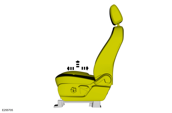
NOTE: Driver seat shown, passenger seat similar.
Move the driver and front passenger seats to the full upward position and forward or rearward to access all the front seat bolts.
 |
-
Depower the SRS .
Refer to: Supplemental Restraint System (SRS) Depowering (501-20B Supplemental Restraint System, General Procedures).
-
Remove the instrument panel upper section.
Refer to: Instrument Panel Upper Section (501-12 Instrument Panel and Console, Removal and Installation).
-
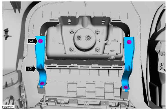
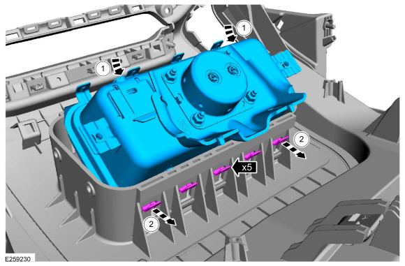
Remove the screws and brackets.
 |
-
-
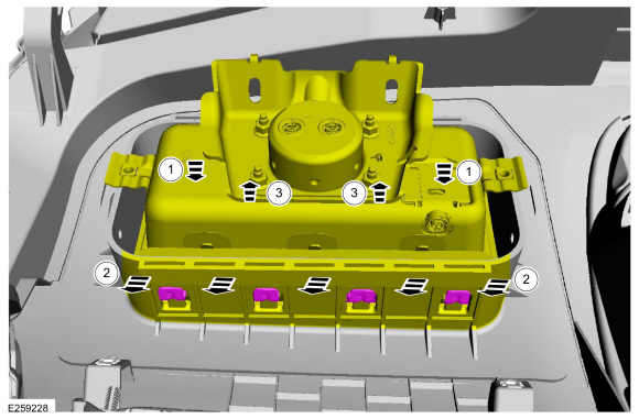
Push the passenger airbag down, into the deployment chute.
-
Pull the deployment chute away from the passenger airbag.
-
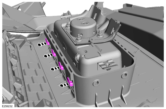
Rotate the passenger airbag out of the deployment chute and disengage the passenger airbag retainers.
-
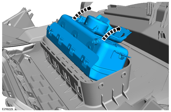
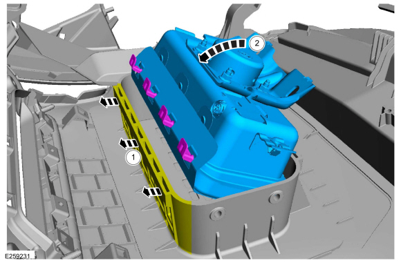
Push the passenger airbag down, into the deployment chute.
 |
-
Continue to rotate the passenger airbag and remove it from the deployment chute.
 |
Installation
WARNING:
Incorrect repair techniques or actions can cause an
accidental Supplemental Restraint System deployment. Make sure the
restraint system is depowered before reconnecting the component. Refer
to the Supplemental Restraint System depowering General Procedure in
section 501-20B. Failure to precisely follow depowering instructions
could result in serious personal injury from an accidental deployment.
-
WARNING:
Before installing the passenger air bag module assembly:
- Inspect the passenger air bag module and instrument panel/deployment chute cavity for any damage or foreign material.
- Remove any foreign material from the passenger air bag module and instrument panel/deployment chute cavity.
- Install new parts if damaged.
-
Position the passenger airbag in to the deployment chute.
-
Engage the passenger airbag retainers.
 |
-
-
Pull the deployment chute out, making room for the passenger airbag to pass.
-
Rotate the passenger airbag down and into the deployment chute.
-
Pull the deployment chute out, making room for the passenger airbag to pass.
 |
-
Engage the passenger airbag retainers to the deployment chute.
 |
-
Install the brackets and screws.
Torque: 22 lb.in (2.5 Nm)
|
-
Install the instrument panel upper section.
Refer to: Instrument Panel Upper Section (501-12 Instrument Panel and Console, Removal and Installation).
-
Repower the SRS .
Refer to: Supplemental Restraint System (SRS) Repowering (501-20B Supplemental Restraint System, General Procedures).
 Removal and Installation - Occupant Classification System (OCS) Sensor - Vehicles With: Rear Seat Side Airbag
Removal
WARNING:
The following procedure prescribes critical repair steps
required for correct restraint system operation during a crash...
 Removal and Installation - Passenger Knee Airbag
Removal
WARNING:
The following procedure prescribes critical repair steps
required for correct restraint system operation during a crash...
Other information:
Ford Ecosport 2014-2025 Service and Repair Manual: Description and Operation - Perimeter Anti-Theft Alarm - System Operation and Component Description
System Operation System Diagram Item Description 1 RKE Antenna 2 Passive Key 3 With Push-Button Start 4 RKE Commands 5 BCM 6 IKT Key 7 Without Push-Button Start 8 RKE Commands 9 Passive Entry Commands 10 ..
Ford Ecosport 2014-2025 Service and Repair Manual: Removal and Installation - Rear Subframe - AWD
Special Tool(s) / General Equipment Flat Headed Screw Driver Transmission Jack Removal NOTICE: Suspension fasteners are critical parts that affect the performance of vital components and systems. Failure of these fasteners may result in major service expense. Use the same or equivalent parts if replacement is necessary. Do not use a replacement part of le..
Categories
- Manuals Home
- 2nd Gen Ford Ecosport Service Manual (2014 - 2025)
- Diagnosis and Testing - Evaporative Emissions
- Removal and Installation - Block Heater
- Description and Operation - Jacking and Lifting - Overview
- Diagnosis and Testing - Body Control Module (BCM)
- General Procedures - Battery Charging
Removal and Installation - Wheel Knuckle Bushing
Special Tool(s) / General Equipment
Hydraulic PressRemoval
NOTE: Removal steps in this procedure may contain installation details.
Remove the wheel knuckle.Refer to: Wheel Knuckle - Vehicles With: Rear Drum Brakes (204-02B Rear Suspension - AWD, Removal and Installation).
Remove the rear toe adjustment retainers and remove the wheel knuckle mounting bracket.
Torque:
Stage 1: 177 lb.in (20 Nm)
Stage 2: 76 lb.ft (103 Nm)