Ford Ecosport: Automatic Transmission - 6-Speed Automatic Transmission – 6F35 / Description and Operation - Intermediate Clutch Assembly
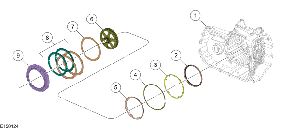
Intermediate (2, 6) Clutch Exploded View
| Item | Description |
| 1 | Transmission case |
| 2 | Intermediate clutch piston |
| 3 | Intermediate clutch piston return spring |
| 4 | Intermediate clutch piston return spring snap ring |
| 5 | Intermediate clutch apply ring |
| 6 | Rear planetary sun gear and shell assembly |
| 7 | Intermediate clutch wave spring |
| 8 | Intermediate clutch assembly |
| 9 | Low/One-Way Clutch (OWC) |
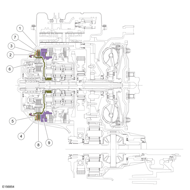
Intermediate (2, 6) Clutch Cutaway View
Intermediate (2, 6) Clutch Mechanical Operation
The intermediate clutch is a brake clutch that holds the rear planetary sun gear and shell assembly. The intermediate clutch is applied in 2nd and 6th gears.
Hydraulic pressure from the regulator valve in the valve body pushes the intermediate clutch piston against the intermediate clutch pack to apply the clutch. The low One-Way Clutch (OWC) works as a pressure plate for the intermediate (2, 6) clutch. The rear planetary sun gear and shell assembly is held stationary to the transmission case as a result of the clutch being applied.
Intermediate (2, 6) Clutch Hydraulic Circuits (Applied)
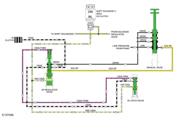
Line pressure is supplied to the 26 regulator valve by the manual valve in the DRIVE and LOW positions. To apply the intermediate (2, 6) clutch, SSC supplies varying solenoid pressure to the 26 regulator and latch valves. As the 26 regulator valve moves, it supplies the intermediate (2, 6) clutch and 26 latch valve with regulated line pressure through the CB26 circuit. The 26 latch valve directs the regulated line pressure to the opposite side of the 26 regulator valve through the CB26 FDBK circuit for gradual intermediate (2, 6) clutch engagement. The intermediate (2, 6) clutch is applied in 2nd and 6th gears.
Intermediate (2, 6) Clutch Hydraulic Circuits (Released)
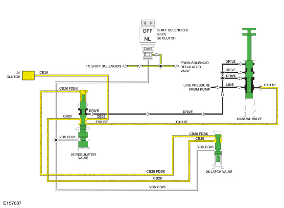
When the intermediate (2, 6) clutch is released in 1st, 3rd, 4th and 5th gears and manual LOW position, solenoid pressure from SSC is removed from the 26 regulator and latch valves which positions the valves to block line pressure and release the intermediate (2, 6) clutch. When the intermediate (2, 6) clutch is released in the PARK, REVERSE or NEUTRAL position, line pressure is not supplied to the 26 regulator valve.
In the released position, exhaust backfill supplied to the 26 clutch regulator valve by the manual valve through the EXH BF circuit is directed to the intermediate (2, 6) clutch and 26 latch valve to fill the unused circuits with unpressurized transmission fluid.
For details on valve body hydraulic circuits and solenoid operation.
For
additional information, refer to: Transmission Description (307-01B
Automatic Transmission - 6-Speed Automatic Transmission – 6F35,
Description and Operation).

 Description and Operation - Low/Reverse Clutch Assembly
Low/Reverse Clutch Exploded View
Item
Description
1
Transmission case
2
Low One-Way Clutch (OWC)
3
Rear planetary carrier
4
Low/reverse clutch pressure plate
5
Low/reverse clutch
6
Low/reverse clutch wav..
Other information:
Ford Ecosport 2014-2025 Service and Repair Manual: General Procedures - Front Fog Lamp Adjustment
Adjustment NOTE: Horizontal aim is not adjustable. Consult your state vehicle inspection center for recommended tolerance ranges for visual aiming. NOTE: Before starting fog lamp adjustment, entry conditions must be met. Vehicle must be on level ground. Tires must be correctly inflated. Vehicle must be normally loaded. ..
Ford Ecosport 2014-2025 Service and Repair Manual: Removal and Installation - Evaporator Inlet and Outlet Manifold - 2.0L Duratec-HE (129kW/175PS)
Removal NOTICE: During the removal of components, cap, tape or otherwise appropriately protect all openings to prevent the ingress of dirt or other contamination. Remove protective materials prior to installation. NOTE: Removal steps in this procedure may contain installation details. Recover the refrigerant. Refer to: Air Conditioning (A/C) System Recovery, E..
Categories
- Manuals Home
- 2nd Gen Ford Ecosport Service Manual (2014 - 2025)
- General Procedures - Battery Charging
- Removal and Installation - Front Seat
- Removal and Installation - Block Heater
- Engine
- Diagnosis and Testing - Powertrain Control Module (PCM) Input and Output Controls
Removal and Installation - Steering Column Shaft
Removal
NOTE: Removal steps in this procedure may contain installation details.
NOTICE: Do not allow the steering column to rotate while the steering column shaft is disconnected or damage to the steering column internal sensor may result.
NOTE: Use a steering wheel holding device (such as Hunter® 28-75-1 or equivalent)
Hold the steering wheel in the straight-ahead position.