Ford Ecosport: Front End Sheet Metal Repairs / Removal and Installation - Front Side Member Section
Special Tool(s) / General Equipment
| Resistance Spotwelding Equipment | |
| Spherical Cutter | |
| Grinder | |
| Air Body Saw | |
| 8 mm Drill Bit | |
| MIG/MAG Welding Equipment | |
| Spot Weld Drill Bit | |
| Locking Pliers |
Materials
| Name | Specification |
|---|---|
| Seam Sealer TA-2-B, 3M™ 08308, LORD Fusor® 803DTM |
- |
Removal
NOTICE: The inner front member section is a tailor-welded blank. No sectioning may be made within 20 mm of the witness line.
NOTICE: The outer side member reinforcement is made of DP600 class steel and may be sectioned providing all sectioning is done 50 mm or more from crush points/convolutes and suspension/drivetrain mounting locations.
NOTICE: Because of the internal baffling and the tailor-welded seam, sectioning of the inner side member is only possible as shown. If damage to the inner side member extends beyond sectioning point and is not repairable, the inner side member must be replaced at factory seams.
NOTE: The following procedure details sectioning of the front portion of the front side member where collision damage is minimal.
LH side shown, RH side similar.-
Depower the SRS .
Refer to: Supplemental Restraint System (SRS) Depowering (501-20B Supplemental Restraint System, General Procedures).
-
Remove the following items:
-
Remove the headlamp assembly.
Refer to: Headlamp Assembly (417-01 Exterior Lighting, Removal and Installation).
-
Remove the front bumper.
Refer to: Front Bumper Cover (501-19 Bumpers, Removal and Installation).
Refer to: Front Bumper (501-19 Bumpers, Removal and Installation).
-
Remove the fender(s).
Refer to: Fender (501-02 Front End Body Panels, Removal and Installation).
Refer to: Fender Splash Shield (501-02 Front End Body Panels, Removal and Installation).
-
Remove the hood.
Refer to: Hood (501-02 Front End Body Panels, Removal and Installation).
-
Remove the cooling module (as equipped).
Refer to: Radiator (303-03B Engine Cooling - 1.5L Duratec (90kW/120PS) – I3, Removal and Installation).
Refer to: Radiator (303-03C Engine Cooling - 2.0L Duratec-HE (129kW/175PS), Removal and Installation).
-
Remove the battery, LH side only.
Refer to: Battery (414-01 Battery, Mounting and Cables, Removal and Installation).
-
Remove the headlamp assembly.
-
Make sure the vehicle is dimensionally correct.
Refer to: Body and Frame (501-26 Body Repairs - Vehicle Specific Information and Tolerance Checks, Description and Operation).
-
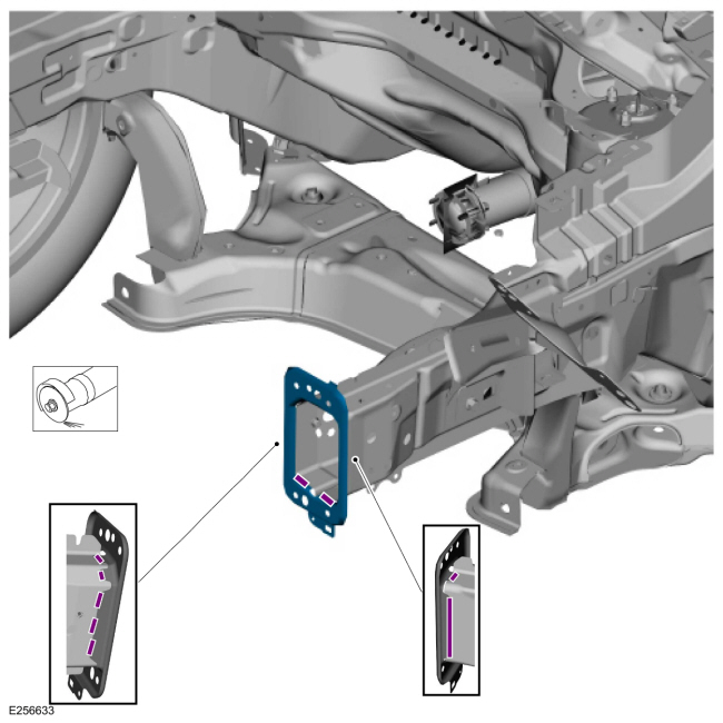
Remove the welds and bumper bracket.
Use the General Equipment: Spherical Cutter
 |
-
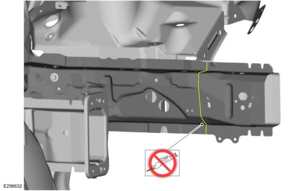
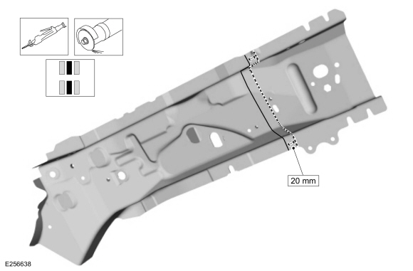
NOTICE: The inner front member section is a tailor-welded blank. No sectioning may be made within 20 mm of the witness line.
NOTICE: Because of the internal baffling and the tailor-welded seam, sectioning of the inner side member is only possible as shown. If damage to the inner side member extends beyond sectioning point and is not repairable, the inner side member must be replaced at factory seams.
Do not section within 20 mm of tailor-weld witness mark.
 |
-
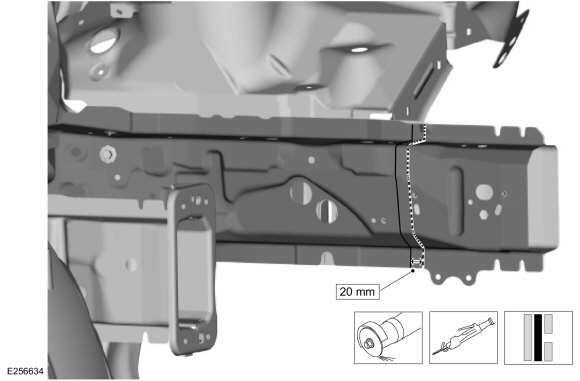
Carefully measure and cut the inner panel only.
Use the General Equipment: Air Body Saw
Use the General Equipment: Spherical Cutter
 |
-
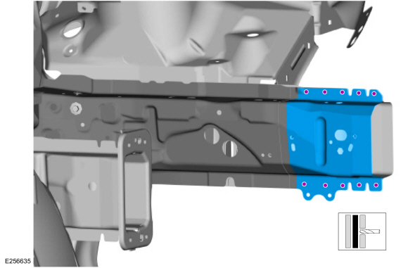
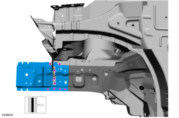
Remove the welds and the inner side member.
Use the General Equipment: Spot Weld Drill Bit
 |
-
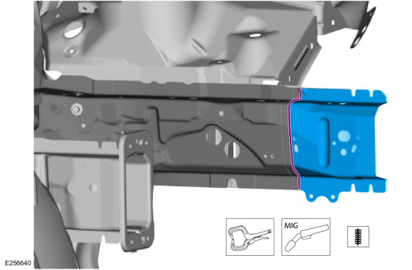
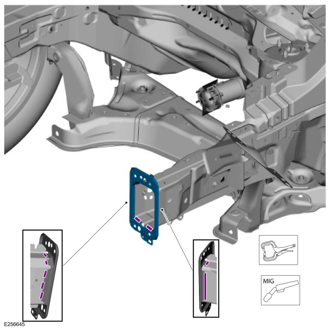
Carefully measure and cut the outer side member section.
Use the General Equipment: Air Body Saw
Use the General Equipment: Spherical Cutter
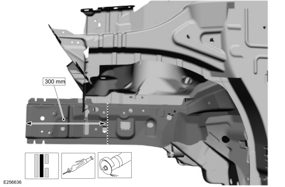 |
-
Remove the welds and outer side member section.
Use the General Equipment: Spot Weld Drill Bit
 |
Installation
NOTICE: The inner front member section is a tailor-welded blank. No sectioning may be made within 20 mm of the witness line.
NOTICE: The outer side member reinforcement is made of DP600 class steel and may be sectioned providing all sectioning is done 50 mm or more from crush points/convolutes and suspension/drivetrain mounting locations.
NOTICE: Because of the internal baffling and the tailor-welded seam, sectioning of the inner side member is only possible as shown. If damage to the inner side member extends beyond sectioning point and is not repairable, the inner side member must be replaced at factory seams.
-
Dress all weld nuggets and rough edges.
Use the General Equipment: Grinder
-
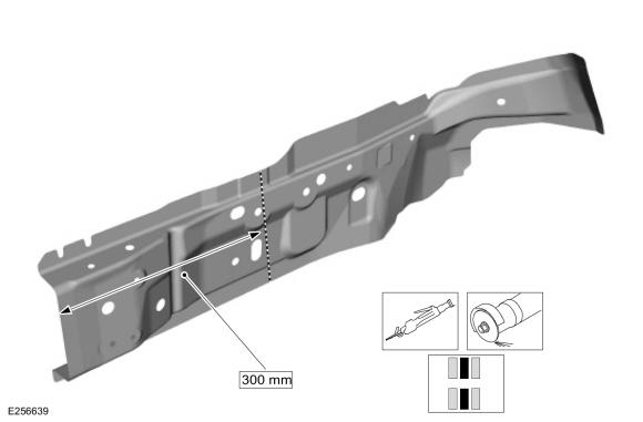
Carefully measure and cut the inner service part to fit repair.
Use the General Equipment: Air Body Saw
Use the General Equipment: Spherical Cutter
 |
-
Carefully measure and cut the outer service part to fit repair.
Use the General Equipment: Air Body Saw
Use the General Equipment: Spherical Cutter
 |
-
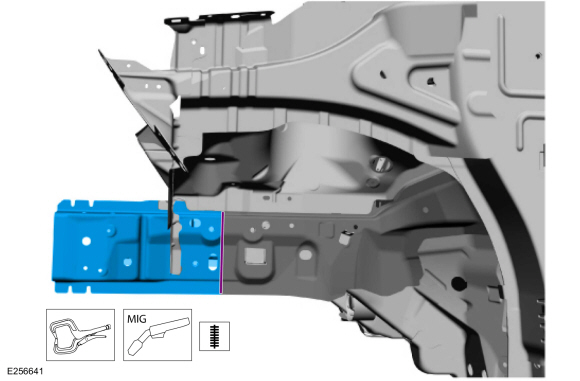
Install, properly position, clamp and seam weld the inner side member section.
Use the General Equipment: Locking Pliers
Use the General Equipment: MIG/MAG Welding Equipment
 |
-
Install, properly position, clamp and seam weld the outer side member section.
Use the General Equipment: Locking Pliers
Use the General Equipment: MIG/MAG Welding Equipment
 |
-
Drill plug weld holes.
Use the General Equipment: 8 mm Drill Bit
 |
-
Install the welds.
Use the General Equipment: MIG/MAG Welding Equipment
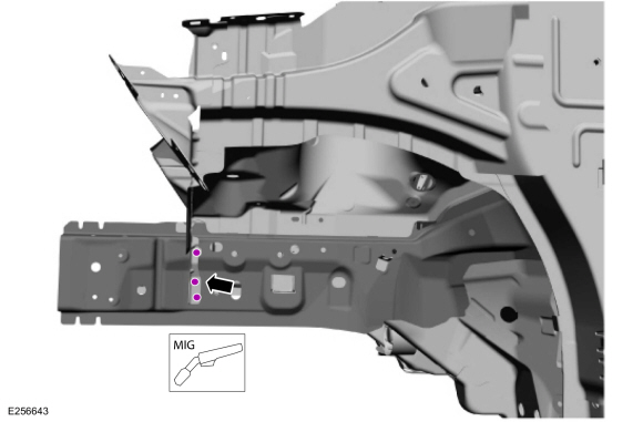 |
-
Install the welds.
Use the General Equipment: Resistance Spotwelding Equipment
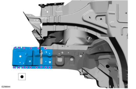 |
-
Install the bumper mounting bracket, clamp in position and weld.
Use the General Equipment: MIG/MAG Welding Equipment
 |
-
Sealing work: All areas must be sealed to production level.
Material: Seam Sealer / TA-2-B, 3M™ 08308, LORD Fusor® 803DTM
-
Refinish using a Ford approved paint system.
-
Restore corrosion protection.
Refer to: Corrosion Prevention (501-25 Body Repairs - General Information, General Procedures).
-
Install the following items:
-
Install the cooling module (as equipped).
Refer to: Radiator (303-03B Engine Cooling - 1.5L Duratec (90kW/120PS) – I3, Removal and Installation).
Refer to: Radiator (303-03C Engine Cooling - 2.0L Duratec-HE (129kW/175PS), Removal and Installation).
-
Install the battery, LH side only.
Refer to: Battery (414-01 Battery, Mounting and Cables, Removal and Installation).
-
Install the fender(s).
Refer to: Fender (501-02 Front End Body Panels, Removal and Installation).
Refer to: Fender Splash Shield (501-02 Front End Body Panels, Removal and Installation).
-
Install the front bumper.
Refer to: Front Bumper Cover (501-19 Bumpers, Removal and Installation).
Refer to: Front Bumper (501-19 Bumpers, Removal and Installation).
-
Install the headlamp assembly.
Refer to: Headlamp Assembly (417-01 Exterior Lighting, Removal and Installation).
-
Install the hood.
Refer to: Hood (501-02 Front End Body Panels, Removal and Installation).
-
Install the cooling module (as equipped).
-
Repower the SRS .
Refer to: Supplemental Restraint System (SRS) Repowering (501-20B Supplemental Restraint System, General Procedures).
 Removal and Installation - Fender Apron Panel Section
Special Tool(s) /
General Equipment
8 mm Drill Bit
MIG/MAG Welding Equipment
Spot Weld Drill Bit
Locking Pliers
Materials
Name
Specification
Seam SealerTA-2-B, 3M™ 08308, LORD Fusor® 803DTM
-
Removal
NOTE:
Factory welds may be substituted with resistance or metal
inert gas (MIG) plug welds...
 Removal and Installation - Front Side Member and Fender Apron Panel LH
Special Tool(s) /
General Equipment
Resistance Spotwelding Equipment
8 mm Drill Bit
MIG/MAG Welding Equipment
Spot Weld Drill Bit
Locking Pliers
Materials
Name
Specification
Seam SealerTA-2-B, 3M™ 08308, LORD Fusor® 803DTM
-
Removal
NOTE:
Factory welds may be substituted with resistance or metal
inert..
Other information:
Ford Ecosport 2014-2025 Service and Repair Manual: General Procedures - Bearing Inspection
Inspection Cratering - fatigue failure Spot glazing - incorrect seating Scratching - dirty engine oil Base exposed - poor lubrication Both edges worn - journal damaged One edge worn - journal tapered or bearing not seated ..
Ford Ecosport 2014-2025 Service and Repair Manual: Removal and Installation - Rear Halfshaft Seal
Special Tool(s) / General Equipment 205-153 (T80T-4000-W) Handle 205-990Installer, Axle SealTKIT-2012A-FLTKIT-2012A-ROW Removal NOTE: Removal steps in this procedure may contain installation details. Remove the rear halfshaft. Refer to: Rear Halfshaft (205-05 Rear Drive Halfshafts, Removal and Installation). NOTE..
Categories
- Manuals Home
- 2nd Gen Ford Ecosport Service Manual (2014 - 2025)
- Diagnosis and Testing - Powertrain Control Module (PCM) Input and Output Controls
- Removal and Installation - Fuel Pump and Sender Unit
- General Procedures - Transmission Fluid Level Check
- Automatic Transmission - 6-Speed Automatic Transmission – 6F35
- Description and Operation - Jacking and Lifting - Overview
Removal and Installation - Front Stabilizer Bar
Special Tool(s) / General Equipment
Tie Rod End Remover Transmission JackRemoval
NOTICE: Suspension fasteners are critical parts that affect the performance of vital components and systems. Failure of these fasteners may result in major service expense. Use the same or equivalent parts if replacement is necessary. Do not use a replacement part of lesser quality or substitute design. Tighten fasteners as specified.
NOTE: Removal steps in this procedure may contain installation details.
NOTICE: Disconnect the b