Ford Ecosport: Front Drive Halfshafts / Removal and Installation - Front Halfshaft LH - 6-Speed Automatic Transmission – 6F35
Special Tool(s) / General Equipment
 |
204-161
(T97P-1175-A)
Installer, Halfshaft TKIT-1997-LM2 TKIT-1997-F/FM2 TKIT-1997-FLM2 |
 |
205-D070
(D93P-1175-B)
Remover, Front Wheel Hub |
 |
211-001
(TOOL-3290-D)
Remover, Tie-Rod End |
Removal
NOTE: Removal steps in this procedure may contain installation details.
-
Remove the wheel and tire.
Refer to: Wheel and Tire (204-04A Wheels and Tires, Removal and Installation).
-
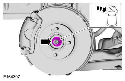
Remove and discard the wheel hub nut.
 |
-
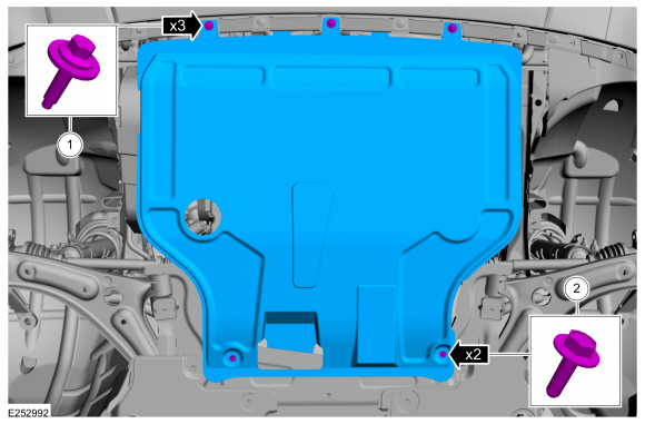
Remove the retainers and the under body shield.
 |
-
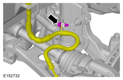
Remove the bolt and position the brake hose aside. WARNING:
Make sure that no load is placed on the brake hose.
WARNING:
Make sure that no load is placed on the brake hose.
 |
-
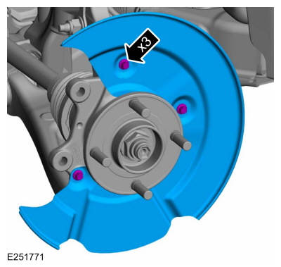
Remove the bolt, detach the retainer and position aside the front wheel speed sensor.
WARNING:
Make sure that the alignment line is not twisted.
 |
-
WARNING:
Make sure that a new bolt is installed.
NOTE: Do not use a prying device or separator fork between the ball joint and the wheel knuckle. Damage to the ball joint or ball joint seal may result. Only use the pry bar by inserting it into the lower arm body opening.
NOTE: Use care when releasing the lower arm and wheel knuckle into the resting position or damage to the ball joint seal may occur.
Remove and discard the lower ball joint nut and bolt.
 |
-
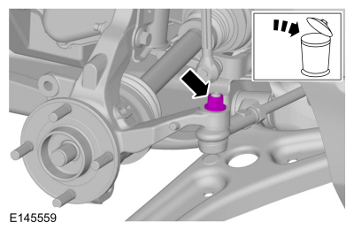
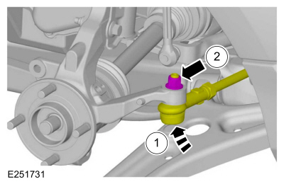
NOTICE: Make sure that the ball joint ball does not rotate.
Remove and discard the tie rod end nut.
 |
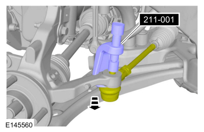
-
Using the special tool, separate the tie rod end from the wheel knuckle.
Use Special Service Tool: 211-001 (TOOL-3290-D) Remover, Tie-Rod End.
 |
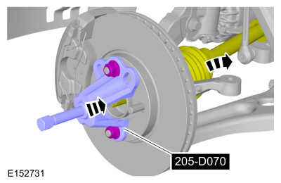
-
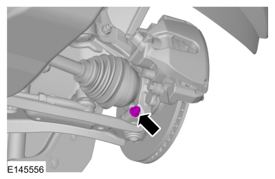
Using the special tool, press the halfshaft from the
front wheel bearing and wheel hub. Support the halfshaft in a level
position.
Use Special Service Tool: 205-D070 (D93P-1175-B) Remover, Front Wheel Hub.
 |
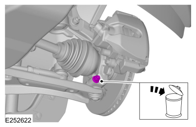
-
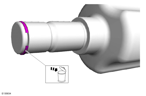
NOTICE: Be prepared to collect escaping fluids.
NOTICE: Make sure that all openings are sealed.
NOTICE: The inner CV joint must not be bent more than 18°.
NOTICE: The outer CV joint must not be bent more than 20°.
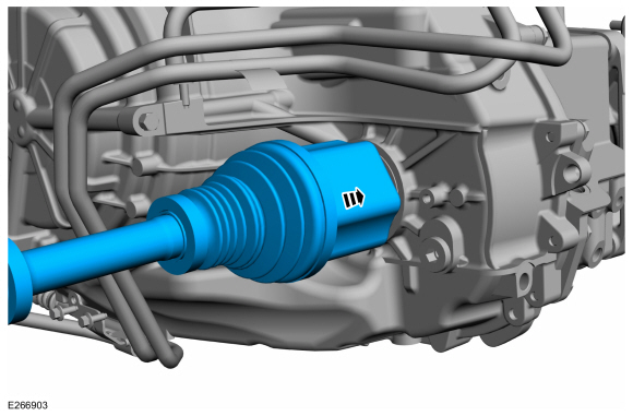
NOTE: Do not pull on the halfshaft. Pull or pry on the inner CV housing only or damage may occur.
By Using the standard pry bar, remove the halfshaft.
 |
-
Remove and discard the halfshaft retaining circlip.
 |
Installation
-
NOTE: Inspect the halfshaft seal for wear or damage and install a new seal if necessary.
If damaged, replace the halfshaft seal.
Refer to: Halfshaft Seal LH (307-01B Automatic Transmission - 6-Speed Automatic Transmission – 6F35, Removal and Installation).
-
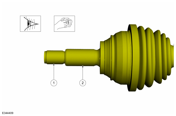
Clean and inspect the inboard end of the halfshaft.
 |
-
Clean and inspect the outboard end of the halfshaft.
 |
-
NOTE: Make sure that a new component is installed.
NOTE: Ensure that the circlip opening is aligned and oriented to 6 o' clock position during installation.
Install the new inner halfshaft retaining circlip.
 |
-
Install the halfshaft until the halfshaft retaining clip is fully seated.
 |
-
Position the halfshaft through the wheel bearing.
 |
-
Using special tool, pull the halfshaft into the front wheel bearing and wheel hub.
Use Special Service Tool: 204-161 (T97P-1175-A) Installer, Halfshaft.
 |
-
NOTICE: Make sure that the ball joint ball does not rotate.
NOTE: Make sure that a new component is installed.
-
Attach the tie rod end to the wheel knuckle.
-
Install the tie rod end nut.
Torque: 39 lb.ft (53 Nm)
-
Attach the tie rod end to the wheel knuckle.
 |
-
NOTE: Make sure that a new component is installed.
Insert the lower ball joint into the wheel knuckle and install a new bolt and nut.
Torque: 38 lb.ft (52 Nm)
 |
-
NOTE: Only tighten the hub nut finger tight at this stage.
Install the new wheel hub nut.
 |
-
WARNING:
Make sure that the alignment line is not twisted.
-
Position back the front wheel speed sensor and install the bolt.
Torque: 80 lb.in (9 Nm)
-
Attach the wheel speed sensor retainer.
-
Position back the front wheel speed sensor and install the bolt.
|
-
Position the brake hose and install the bolt.
WARNING:
Make sure that no load is placed on the brake hose.
Torque: 18 lb.ft (25 Nm)
|
-
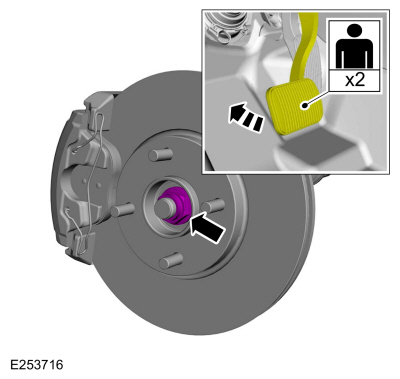
NOTICE: Do not tighten the front wheel hub nut with the vehicle on the ground. The nut must be tightened to specification before the vehicle is lowered onto the wheels. Wheel bearing damage will occur if the wheel bearing is loaded with the weight of the vehicle applied.
NOTICE: Install and tighten the new wheel hub nut to specification in a continuous rotation. Always install a new wheel hub nut after loosening or when not tightened to specification in a continuous rotation or damage to the components may occur.
NOTE: Apply the brake to keep the halfshaft from rotating.
While an assistant applies the brake, install the new wheel hub nut.
Torque: 188 lb.ft (255 Nm)
 |
-
Check the transmission fluid level.
Refer to: Transmission Fluid Level Check (307-01B Automatic Transmission - 6-Speed Automatic Transmission – 6F35, General Procedures).
-
Install the wheel and tire.
Refer to: Wheel and Tire (204-04A Wheels and Tires, Removal and Installation).
-
Install the underbody shield and the retainers.
|
 Removal and Installation - Front Halfshaft RH - 2.0L Duratec-HE (125kW/170PS) – MI4, AWD
Special Tool(s) /
General Equipment
204-161
(T97P-1175-A)
Installer, HalfshaftTKIT-1997-LM2TKIT-1997-F/FM2TKIT-1997-FLM2
205-D070
(D93P-1175-B)
Remover, Front Wheel Hub
211-001
(TOOL-3290-D)
Remover, Tie-Rod End
Removal
NOTE:
Removal steps in this procedure may contain installation details...

Other information:
Ford Ecosport 2014-2024 Service and Repair Manual: Removal and Installation - Front Stabilizer Bar Bushing
Removal NOTICE: Suspension fasteners are critical parts that affect the performance of vital components and systems. Failure of these fasteners may result in major service expense. Use the same or equivalent parts if replacement is necessary. Do not use a replacement part of lesser quality or substitute design. Tighten fasteners as specified. NOTE: Removal steps in ..
Ford Ecosport 2014-2024 Service and Repair Manual: Description and Operation - Roof Opening Panel - System Operation and Component Description
System Operation Roof Opening Operation The roof opening panel assembly uses an integrated motor and module to operate the roof opening panel. The roof opening panel switch is located in the overhead console. Actuating the switch supplies a voltage signal to the roof opening panel motor. To open the sliding glass panel, press and release the rear of the control switch. The roo..
Categories
- Manuals Home
- 2nd Gen Ford Ecosport Service Manual (2014 - 2024)
- Removal and Installation - Block Heater
- Removal and Installation - Catalytic Converter
- Climate Control System - General Information
- Engine
- Removal and Installation - Roof Rail
Removal and Installation - Brake Disc Shield
Removal
NOTE: Removal steps in this procedure may contain installation details.
Remove the brake disc.Refer to: Brake Disc (206-03 Front Disc Brake, Removal and Installation).
Remove the bolts and brake disc.
Torque: 80 lb.in (9 Nm)