Ford Ecosport: Rear End Sheet Metal Repairs / Removal and Installation - Front Floor Panel Upper Rear Crossmember
Special Tool(s) / General Equipment
| 8 mm Drill Bit | |
| MIG/MAG Welding Equipment | |
| Spot Weld Drill Bit | |
| Locking Pliers |
Materials
| Name | Specification |
|---|---|
| Seam Sealer TA-2-B, 3M™ 08308, LORD Fusor® 803DTM |
- |
Removal
NOTE: Left hand (LH) side shown, right hand (RH) side similar.
NOTE: Roof and body side removed for clarity.
NOTE: Factory welds may be substituted with resistance or metal inert gas (MIG) plug welds. Resistance welds may not be placed directly over original location. They must be placed adjacent to original location and match factory welds in quantity. Metal inert gas (MIG) plug welds must equal factory welds in both location and quantity.
NOTE: Adequately protect all adjacent areas against cutting, grinding and welding procedures.
-
Depower the SRS .
Refer to: Supplemental Restraint System (SRS) Depowering (501-20B Supplemental Restraint System, General Procedures).
-
If Required:
Dimensionally restore the vehicle to pre-damage condition.
Refer to: Body and Frame (501-26 Body Repairs - Vehicle Specific Information and Tolerance Checks, Description and Operation).
-
Remove the front seat.
Refer to: Front Seat (501-10A Front Seats, Removal and Installation).
-
Remove the center console.
Refer to: Floor Console (501-12 Instrument Panel and Console, Removal and Installation).
-
Remove the B-pillar trim panels.
Refer to: B-Pillar Trim Panel (501-05 Interior Trim and Ornamentation, Removal and Installation).
-
Position aside the weather strip, release the clips and remove the LH instrument panel side trim panel.
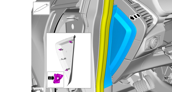 |
-
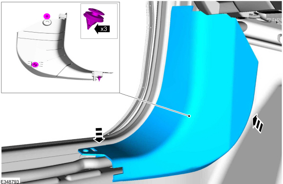
Release the retainers and remove the LH lower cowl trim panel.
 |
-
Position the carpet and all wiring harnesses away from the working area.
-
Remove the welds.
Use the General Equipment: Spot Weld Drill Bit
 |
-
Remove the welds.
Use the General Equipment: Spot Weld Drill Bit
 |
-
NOTE: Pay particular attention the location of adhesives, sealers and NVH materials to aid in installation.
Remove the crossmember.
 |
Installation
NOTE: Left hand (LH) side shown, right hand (RH) side similar.
NOTE: Roof and body side removed for clarity.
NOTE: Factory welds may be substituted with resistance or metal inert gas (MIG) plug welds. Resistance welds may not be placed directly over original location. They must be placed adjacent to original location and match factory welds in quantity. Metal inert gas (MIG) plug welds must equal factory welds in both location and quantity.
NOTE: Adequately protect all adjacent areas against cutting, grinding and welding procedures.
-
Drill plug weld holes in the replacement rear crossmember.
Use the General Equipment: 8 mm Drill Bit
 |
-
Install, properly position and clamp the rear crossmember.
Use the General Equipment: Locking Pliers
 |
-
Install the welds.
Use the General Equipment: MIG/MAG Welding Equipment
 |
-
Install the welds.
Use the General Equipment: MIG/MAG Welding Equipment
 |
-
Dress all welds as required using typical metal finishing techniques.
-
Seam Sealing:
All seams must be sealed to production level.
Material: Seam Sealer / TA-2-B, 3M™ 08308, LORD Fusor® 803DTM
-
Refinish the entire repair using a Ford approved paint system.
-
Reposition all wiring harnesses and the carpet to original locations.
-
Install the center console.
Refer to: Floor Console (501-12 Instrument Panel and Console, Removal and Installation).
-
Install the front seat.
Refer to: Front Seat (501-10A Front Seats, Removal and Installation).
-
Install the LH lower cowl trim panel.
 |
-
Install the LH instrument panel side trim panel, Install the weather strip.
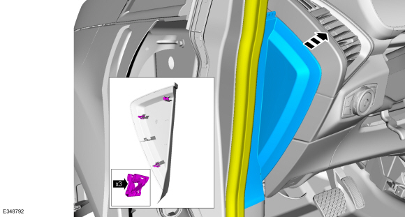 |
-
Install the B-pillar trim panels.
Refer to: B-Pillar Trim Panel (501-05 Interior Trim and Ornamentation, Removal and Installation).
-
Restore corrosion protection.
Refer to: Corrosion Prevention (501-25 Body Repairs - General Information, General Procedures).
-
Repower the SRS .
Refer to: Supplemental Restraint System (SRS) Repowering (501-20B Supplemental Restraint System, General Procedures).
 Removal and Installation - Front Floor Panel Upper Front Crossmember
Special Tool(s) /
General Equipment
8 mm Drill Bit
MIG/MAG Welding Equipment
Spot Weld Drill Bit
Locking Pliers
Materials
Name
Specification
Seam SealerTA-2-B, 3M™ 08308, LORD Fusor® 803DTM
-
Removal
NOTE:
Left hand (LH) side shown, right hand (RH) side similar...
 Removal and Installation - Rear Exhaust Mounting Bracket
Special Tool(s) /
General Equipment
8 mm Drill Bit
MIG/MAG Welding Equipment
Spot Weld Drill Bit
Locking Pliers
Removal
NOTE:
Factory welds may be substituted with resistance or metal
inert gas (MIG) plug welds...
Other information:
Ford Ecosport 2014-2024 Service and Repair Manual: Removal and Installation - Rear Door Glass Run and Bracket
Removal NOTE: Removal steps in this procedure may contain installation details. NOTE: LH side shown, RH side similar. Remove the rear door trim panel. Refer to: Rear Door Trim Panel (501-05 Interior Trim and Ornamentation, Removal and Installation)...
Ford Ecosport 2014-2024 Service and Repair Manual: Removal and Installation - Driveshaft
Special Tool(s) / General Equipment Flat Headed Screw Driver Center Punch Copper Hammer Removal NOTE: The max articulation of any CV is 5 degrees. If the CV or any U-joint of the driveshaft is articulated further then the max allowable degrees damage may occur...
Categories
- Manuals Home
- 2nd Gen Ford Ecosport Service Manual (2014 - 2024)
- Removal and Installation - Front Seat
- Removal and Installation - Body Control Module (BCM)
- Service Information
- Removal and Installation - Fuel Pump and Sender Unit
- Diagnosis and Testing - Evaporative Emissions
Removal and Installation - Wheel Knuckle Bushing
Special Tool(s) / General Equipment
Hydraulic PressRemoval
NOTE: Removal steps in this procedure may contain installation details.
Remove the wheel knuckle.Refer to: Wheel Knuckle - Vehicles With: Rear Drum Brakes (204-02B Rear Suspension - AWD, Removal and Installation).
Remove the rear toe adjustment retainers and remove the wheel knuckle mounting bracket.
Torque:
Stage 1: 177 lb.in (20 Nm)
Stage 2: 76 lb.ft (103 Nm)